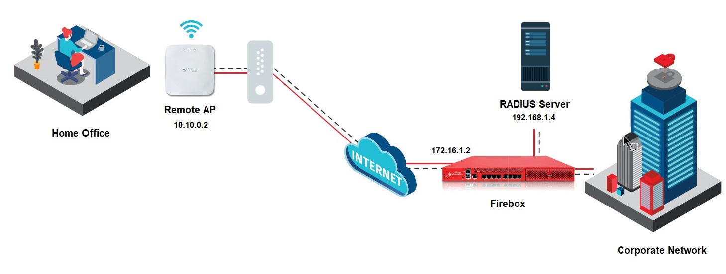
Configure a Firebox VPN for a Remote Access Point
Applies To: Wi-Fi Cloud-managed Access Points (AP125, AP225W, AP325, AP327X, AP420)
Remote Access Point functionality is only supported on the AP225W, AP327X, and AP420.
You can use the WatchGuard Firebox as an IPSec VPN endpoint for the remote AP.
A remote AP requires a virtual IP address to create the VPN tunnel. When you use a remote AP with the Firebox, you must use the Mobile VPN with IKEv2 solution on a Firebox to provide a virtual IP address for the remote AP.
Configure a Firebox VPN for a Remote Access Point
To configure a remote AP for a Firebox VPN, you must:
- Configure a Firebox VPN with IKEv2
- Configure TCP Maximum Segment Size (MSS) Settings on the Firebox
- Create an IPSec VPN Tunnel Profile in Wi-Fi Cloud
- Add the IPSec VPN Tunnel to a Wi-Fi Cloud SSID Profile
- Deploy the SSID to the Remote AP in Wi-Fi Cloud
Configure a Firebox VPN with IKEv2
For more information about how to configure the Mobile VPN with IKEv2 on the Firebox, see Mobile VPN with IKEv2.
To configure a Firebox Mobile VPN with IKEv2, from Fireware Web UI:
- Log in to the Firebox.
- Select VPN > Mobile VPN.
- In the IKEv2 section, click Configure.
Select Manually Configure if this is the first time you are setting up IKEv2. - Select the Activate Mobile VPN with IKEv2 check box.
- Select the Networking tab.
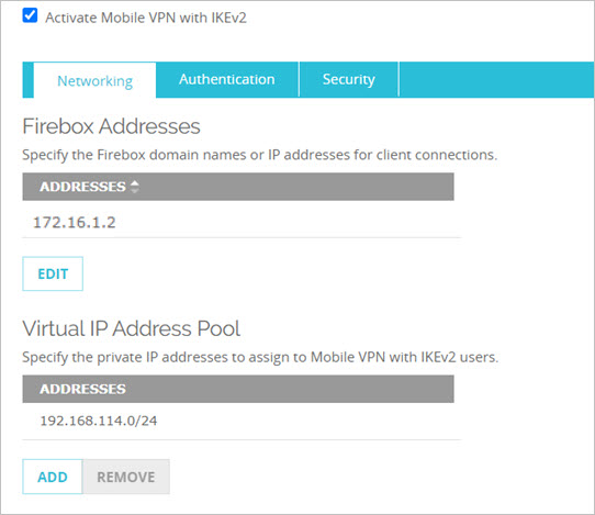
- In the Firebox Addresses section, click Edit, then type an IP address or domain name for connections from Mobile VPN with IKEv2 users. This is the Remote Endpoint address you will specify in the Wi-Fi Cloud IPSec tunnel VPN configuration. For example: 172.16.1.2
- In the Virtual IP Address Pool section, use the default settings, or click Add and specify an IP address pool to assign to Mobile VPN with IKEv2 users.
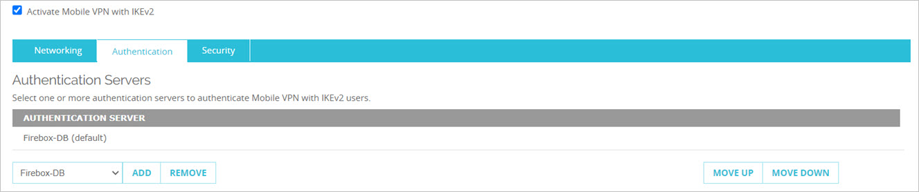
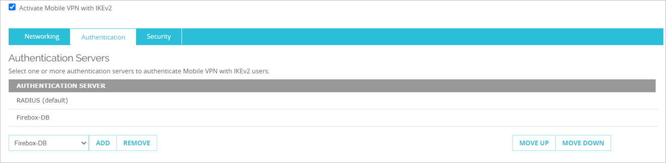
- Select the Authentication tab.
- You can use the default Firebox-DB authentication or RADIUS authentication. Firebox-DB Authentication

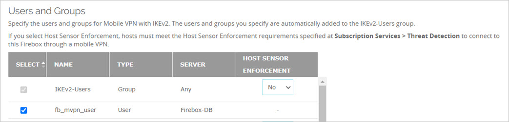
If you use the default Firebox-DB authentication for the Remote Access Point VPN, specify a user for Mobile VPN with IKEv2. The user that you specify is automatically added to the IKEv2-Users group.
In the Users and Groups section, select Firebox-DB and User from the drop-down lists, then click Add.
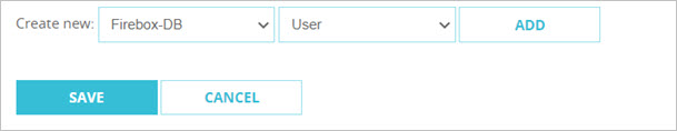
In the Name and Description text boxes, type a name and description for the Firebox user. For example: fb_mvpn_user.
Type and confirm a Password for the Firebox-DB user.
To save the user, click Save.
Make sure the user you created is selected in the configuration.
 RADIUS Authentication
If you use RADIUS, from the drop-down list, select RADIUS, then click Add. For more information on how to add a RADIUS server, see Configure RADIUS Server Authentication.
Make sure the authentication method you choose is the first authentication server in the list order.
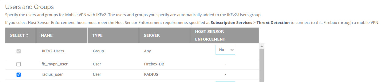
Specify the users and groups for Mobile VPN with IKEv2. The users and groups you specify are automatically added to the IKEv2-Users group.
For example, if you use RADIUS authentication, in the Users and Groups section, select RADIUS and User from the drop-down lists, then click Add.
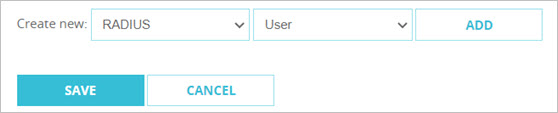
In the Name and Description text boxes, type a name and description for the RADIUS user. For example: radius_user.
To save the user, click Save.
Make sure the user you created is selected in the configuration.
- Select the Security tab, then select Phase 1 Settings.
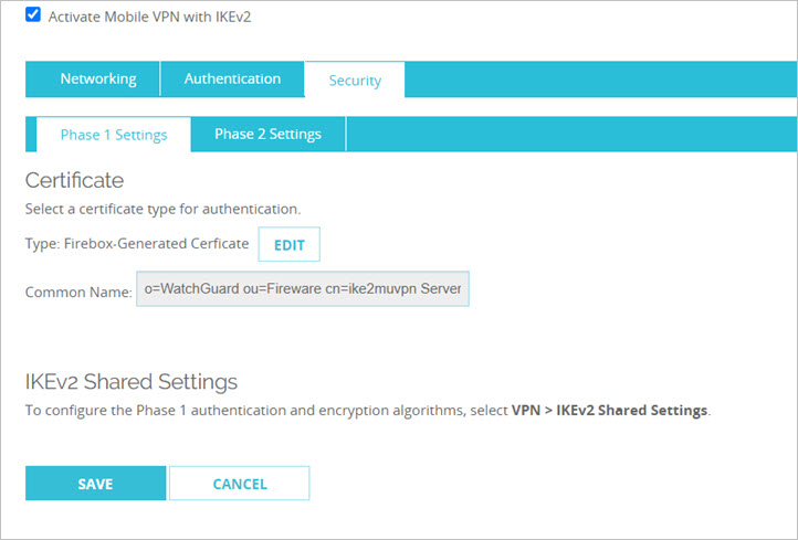
- Click Edit.
- Select a Firebox-Generated Certificate for client authentication from the drop-down list.
- Specify the server name or IP address for client connections.
This information is included in the Firebox-generated certificate. - Click Add. Click OK.
You can configure Phase 1 authentication and encryption algorithms for the Firebox VPN in VPN > IKEv2 Shared Settings.
- Select the Phase 2 Settings tab.
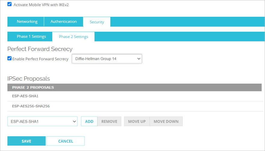
- Select the Enable Perfect Forward Secrecy check box.
- Select Diffle-Hellman Group 14 from the drop-down list.
- In the IPSec Proposals section, select ESP-AES256-SHA256. Click Add.
- Click Save.
Configure TCP Maximum Segment Size (MSS) Settings on the Firebox
To optimize communications between wireless clients and the Firebox over the Remote Access Point VPN tunnel, you must reduce the TCP maximum segment size value in the Firebox global settings. The Firebox uses this value when a VPN tunnel connection is established. For the Remote Access Point VPN, you must set this value to 1360 bytes.
The TCP maximum segment size is a global setting and applies to all Firebox tunnel communications.
To configure the TCP maximum segment size option, from Fireware Web UI:
- Log in to the Firebox.
- Select System > Global Settings.
- Select the Networking tab.
- In the TCP maximum segment size control section, select Limit to, then type 1360.
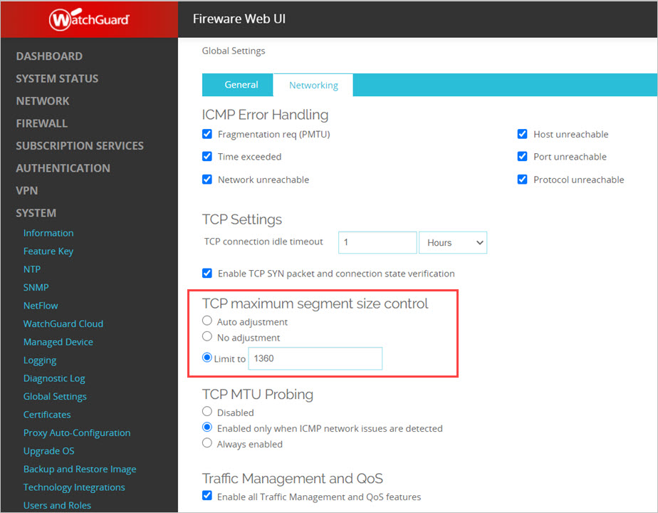
- Click Save.
Create an IPSec VPN Tunnel Profile in Wi-Fi Cloud
To create an IPSec VPN tunnel profile for a remote Access Point in Wi-Fi Cloud:
- Open Discover.
- Select Configure > WiFi, then select the Tunnel Interface tab.
- Click Add Tunnel Interface.
- From the Tunnel Type drop-down list, select VPN with IPSec.
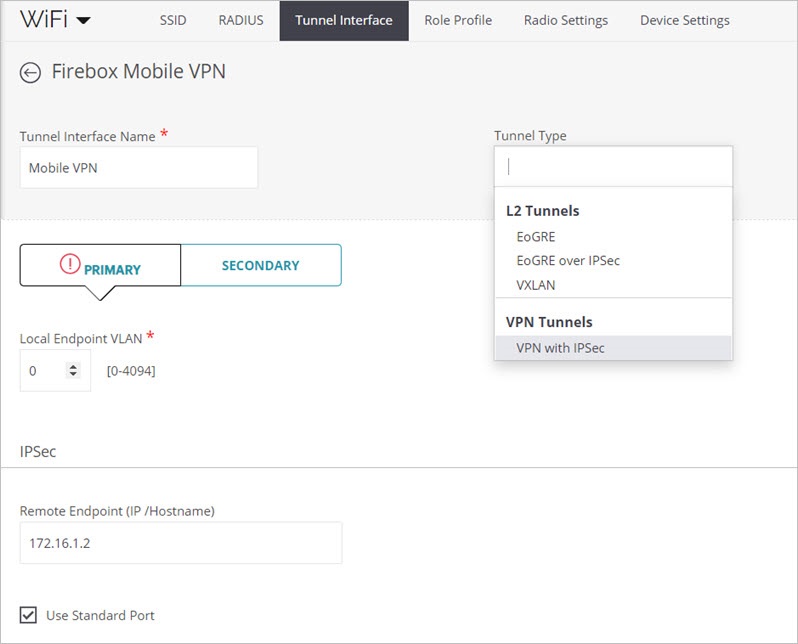
- In the Tunnel Interface Name text box, type a descriptive name for the tunnel.
- Specify the primary Remote Endpoint IP address or host name for your corporate network servers.
This is the remote endpoint IP address you configured for the Firebox Mobile VPN. For example: 172.16.1.2
- Select the Use Standard Port check box to use these standard IKE UDP ports:
- Port 500 if no NAT detected
- Port 4500 if NAT is detected between two endpoints
If you use a custom port for IKE connections, clear the Use Standard Port check box and specify the custom port number in the Port field.
- In the Phase 1 Parameters, select IKE Version 2.
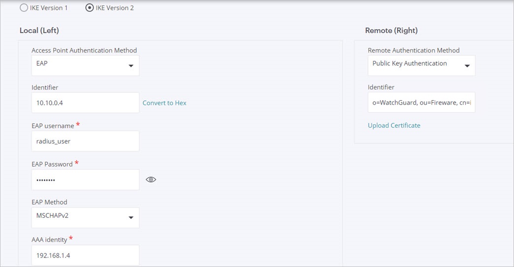
- From the Access Point Authentication Method drop-down list, select EAP.
- In the Local (Left) section, configure these settings:
- In the Identifier text box, type the IP address for the remote AP. For example: 10.10.0.2.
For a stable IPSec VPN tunnel connection, we recommend you use a static IP address for the remote AP. For more information on how to set a static IP address, see How to set a static IP address for an AP in WatchGuard Wi-Fi Cloud.
- Type the EAP Username and Password. Use the user name and password of the user you created for authentication on the Firebox.
For example, for Firebox-DB authentication, type the user name you configured for the Firebox authentication user, such as fb_mvpn_user.
For RADIUS authentication, type the user name you configured for the RADIUS authentication user, such as radius_user. - From the EAP Method drop-down list, select MSCHAPv2.
- In the AAA Identity text box, type the IP address of your Firebox if you use Firebox authentication. If you use RADIUS authentication, type the IP address of your RADIUS server. For example: 192.168.1.4
- In the Remote (Right) section, configure these settings:
- From the Remote Authentication Method drop-down list, select Public Key Authentication.
- In the Identifier text box, type the Common Name from the VPN Phase 1 Settings on your Firebox.
For example: o=WatchGuard, ou=Fireware, cn=ike2muvpn Server - Click Upload Certificate, and select the certificate file you downloaded from the Firebox. To download the Firebox certificate:
- Log in to the Firebox.
- Select VPN > Mobile VPN > IKEv2.
- Click Client Profile.
- Click Download.
- In the files you downloaded, the rootca.pem file is the certificate that you must upload in Discover.
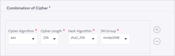
- In the Combination of Cipher section, specify the encryption method you configured on the Firebox.
- In the Phase 2 Parameters, select ESP, then specify the Combination of Cipher settings with the encryption method you configured on the Firebox.
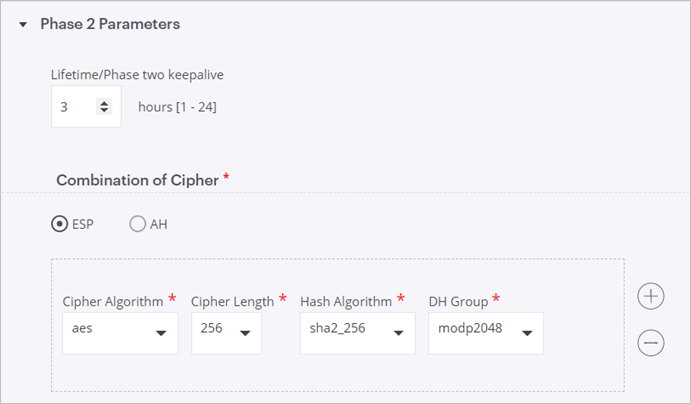
The Diffie Hellman Group 14 that is configured on the Firebox corresponds to modp2048 in the Wi-Fi Cloud tunnel interface configuration. For more information, see About Diffie-Hellman Groups.
- Click Save.
Add the IPSec VPN Tunnel to a Wi-Fi Cloud SSID Profile
To add the IPSec VPN tunnel to an SSID profile in Wi-Fi Cloud:
- Open Discover.
- Select Configure > WiFi, then select the SSID tab.
- Select an SSID.
- In the SSID settings, select the Network tab.
- Select VPN Tunnel.
- From the Tunnel Interface drop-down list, select the tunnel that you configured.
For example: Mobile VPN
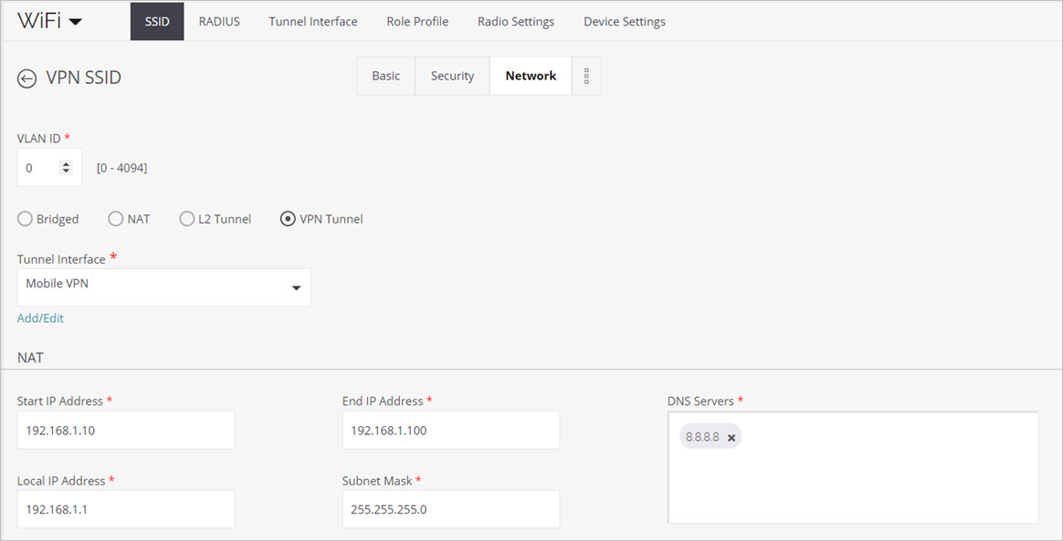
- Specify the NAT settings for the SSID. Wi-Fi clients receive an IP address from this address pool when they associate to the AP.
- To split the traffic between the corporate network and the public Internet, select the Split Tunnel for Client Traffic check box.
Only corporate-bound traffic is sent through the tunnel, while Internet traffic bypasses the tunnel. You can specify the subnets that are accessible through the tunnel.
- To enable RADIUS messages between the remote AP and a RADIUS authentication server located on the corporate network behind the remote tunnel endpoint, select the Use Tunnel for RADIUS Message check box.
802.1X authentication must be enabled on the SSID to enable RADIUS messages over the tunnel.
The Remote AP VPN tunnel does not support IPv6 communications. The RADIUS server must have an IPv4 address to tunnel RADIUS messages between the AP and the RADIUS server.
Deploy the SSID to the Remote AP in Wi-Fi Cloud
To deploy an SSID to a remote AP, make sure the SSID with the VPN tunnel you configured is applied to the correct location for the remote AP, such as a remote worker home office AP or a branch office AP.