Configure Managed VPNs
Applies To: Locally-managed Fireboxes
Before you add a managed VPN, make sure you have added all the external interfaces you want to use for the VPN to the Fireboxes that you select as the hub and spoke devices. The external interfaces on the hub device must have static IP addresses. To apply a firewall policy other than the default Any policy, you must also configure that policy on each spoke device before you add the Firebox as a spoke device.
When you add a managed VPN in Dimension, you can select whether to use a Traditional BOVPN or a Virtual Interface BOVPN. If you select a Virtual Interface BOVPN, you can use dynamic routing. Requirements to use dynamic routing include:
- Dynamic routing is only supported when the Virtual Interface BOVPN option is selected
- Hub devices can use both static and dynamic routing
- Spoke devices can only use one routing option
- Both the hub and spoke devices must use mixed routing mode
- IP addresses for dynamic routing must not be used for any other purpose
- IP addresses specified for dynamic routing must be unique addresses not used for another VPN managed by the same instance of Dimension
- The dynamic routing configuration for each device must be configured in the Firebox device configuration file; Dimension does not manage the dynamic routing configuration
For more information about how to configure an external interface on your Firebox, go to Configure an External Interface.
For more information about how to configure dynamic routing on your Firebox, go to About Dynamic Routing.
For more information about how to add a policy to your Firebox device configuration file, go to Add Policies to Your Configuration.
For more information about the types of VPN tunnels you can create with Dimension, go to Manage VPNs for Connected Fireboxes.
Add a Managed VPN
When you add a managed VPN, you specify the settings for the hub device and then add spoke devices to the VPN. The VPN settings you specify in the wizard are applied to the hub and spoke devices only after you complete the Spoke Device wizard.
Add a Hub Device
To add a hub device:
- Select Home > VPNs.
The VPNs page opens. - Click Add.
The Create VPN wizard starts, with the Hub Device page selected.

- From the Hub Device drop-down list, select the Firebox to be the hub device in the VPN (central location of the VPN).
Only Fireboxes that are managed by Dimension appear in this list. - From the BOVPN Type drop-down list, select an option:
- Traditional BOVPN (Recommended)
- Virtual Interface BOVPN
- Click Next.
The Settings page opens. - In the VPN Name text box, type the name for the managed VPN. Tip!
- Click Next.
The External Interfaces page opens. - From the External Interfaces list, select the external interfaces on the hub device to use for traffic through the BOVPN tunnel. The external interfaces you select must have static IP addresses.
By default, the list includes all the external interfaces configured on the Firebox. You can add or remove external interfaces in the list, or change the order the interfaces appear in the list.- To add external interfaces to the list, click
 and select the interfaces to add. Click OK.
 - To remove external interfaces from the list, click
 and select the interfaces to remove.
 - To change the order of the external interfaces in the list, select an interface and click
 or
or  .
.
Make sure the first interface in the list is the primary external interface.
- To add external interfaces to the list, click
- Click Next.
The VPN Resources page opens. - If you selected a Virtual Interface BOVPN and use dynamic routing, to specify a virtual interface IP address, in the Virtual Interface Address text box, type the IPv4 address of the virtual interface.
- If you do not use dynamic routing, or if you use dynamic routing but selected a Traditional BOVPN, to specify the IP addresses on the hub device that spoke devices can connect to, click .
The Add VPN Resource dialog box opens.- In the IP Address text box, type the IP address of the external interface on the hub device.
- From the Direction drop-down list, select the direction traffic can travel over this IP address:
- Hub-to-Spoke
- Spoke-to-Hub
- Click OK.
The IP address appears in the VPN Resources list.
- Click Finish.
The Create VPN wizard finishes, and the VPN appears on the Hub and Spoke VPN page.
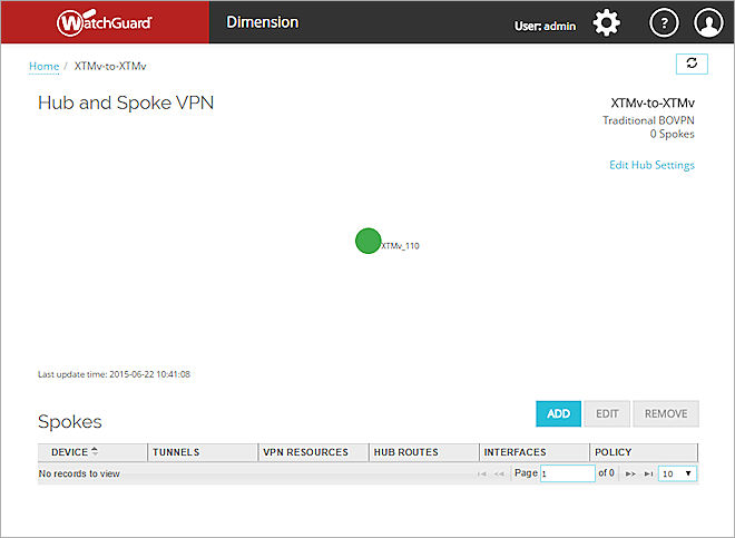
Next, you can add one or more spoke devices to your VPN.
Add a Spoke Device
From the Hub and Spoke VPN page for the hub device, you can add one or more spoke devices to the managed VPN. For more information about the different configuration options for hub-and-spoke VPNs, see Manage VPNs for Connected Fireboxes.
To add a spoke device to the managed VPN:
- In the Spokes section, click Add.
The Add Spoke Gateway wizard opens, with the Spoke Device page selected.
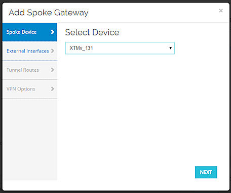
- From the Select Device drop-down list, select the managed Firebox for this spoke of the VPN.
You cannot select the same Firebox you selected for the Hub device. - Click Next.
The External Interfaces page opens. - From the External Interfaces list, select the external interfaces on the spoke device to use for traffic through the BOVPN tunnel.
By default, the list includes all the external interface configured on the Firebox. You can add or remove external interfaces in the list, or change the order the interfaces appear in the list.- To add external interfaces to the list, click and select the interfaces to add. Click OK.
- To remove external interfaces from the list, click and select the interfaces to remove.
- To change the order of the external interfaces in the list, select an interface and click or .
Make sure the first interface in the list is the primary external interface.
- To add external interfaces to the list, click
- Click Next.
The Tunnel Routes page opens. - From the Tunnel Mode drop-down list, select a method to send traffic over the managed VPN:
- Specify Traffic Routes Over VPN (Recommended)
- Send All Traffic Over VPN
- Specify Virtual Interface Address
(Only available if the hub device uses a Virtual Interface Address)
- If you select Specify Virtual Interface Address, in the Virtual Interface Address text box, type the Virtual Interface IP address.
- If you select Specify Traffic Routes Over VPN (Recommended) or Send All Traffic Over VPN, to add one or more IP addresses to the Route From list, click .
The Add VPN Resource dialog box opens.- In the IP Address text box, type the IP address of the external interface on the spoke device.
- From the Direction drop-down list, select the direction traffic can travel over this IP address:
- Bi-directional (Recommended)
- Hub-to-Spoke
- Spoke-to-Hub
- To enable one-to-one NAT for this resource, select the Enable 1:1 NAT check box and type the host address or network address to use.
- Click OK.
The IP address appears in the Route From list.
- (Specify Traffic Routes Over VPN only) In the Route To list, the VPN Resource IP addresses of the hub device appear. You can change which IP addresses on the hub device the spoke device can connect to:
- To remove an IP address from the Route To list, select the interface and click .
- To add an IP address to the Route To list, click and select the interface to add. Click OK.
- To remove an IP address from the Route To list, select the interface and click
- Click Next.
The VPN Options page opens. - From the Firewall Policies drop-down list, select the policy in your spoke device configuration file to apply to the traffic through the managed VPN. The default options are:
- Any (Recommended) — This option creates the Any policy in your device configuration file
- None — No policy will be applied to the traffic through the managed VPN
- Click Finish.
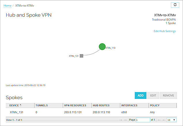
Dimension builds the managed VPN tunnel between the two Fireboxes, and the spoke device appears in the Spokes list and the Hub and Spoke VPN Map.
To add another spoke device to the managed VPN, repeat Steps 1-13.
The hub device and each spoke device appear on the Hub and Spoke VPN page in the VPN map. The hub device is a round icon and each spoke device is a square icon. Each spoke device is connected to the hub device by a line.
The line that connects the hub and spoke devices indicates the status of the connection:
- Solid — The connection between the hub and spoke devices is active
- Dotted — The connection between the hub and spoke devices is inactive
The color of each icon indicates the status of the device:
- Green frame — At least one active tunnel
- Green solid — All tunnels are active
- Grey — No VPN health data
- Red — No active tunnels
Edit a Managed VPN
After you have added a hub device to create a managed VPN, you can edit the managed VPN to change the settings of the hub device or a spoke device, or add another spoke device to the managed VPN.
The settings you specify when you edit a managed VPN are applied to the hub and spoke devices after you complete the Spoke Device wizard. If you only edit the settings for the Hub device, configuration changes are only applied to the Hub and Spoke devices after you run the Spoke Device wizard again.
To edit a managed VPN:
- Select Home > VPNs.
The VPNs page opens.
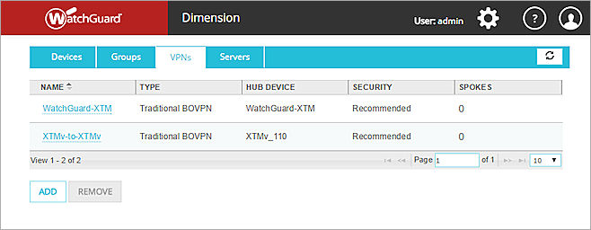
- From the VPNs list, select a managed VPN to edit.
The Hub and Spoke VPN page opens, with the VPN map and the list of spoke devices.
- To edit the hub device, click Edit Hub Settings and follow the instructions in the Edit a Hub Device section.
- To edit a spoke device, select the spoke device to edit and follow the instructions in the Edit a Spoke Device section.
- To remove a spoke device, select the spoke device to remove and follow the instructions in the Remove a Spoke Device section.
Edit a Hub Device
After you have added a hub device to the managed VPN, you can edit the hub device to change the Phase 1 settings, Phase 1 transform, and Phase 2 settings specified for the hub device. You also modify any of the settings you specified when you added the managed VPN, except for the name of the hub device and the BOVPN type.
To edit the settings for a hub device:
- At the top-right side of the Hub and Spoke VPN page, click Edit Hub Settings.
The Edit VPN wizard opens with the Hub Device page selected. - Select a tab to modify the Settings, External Interfaces, or VPN Resources specified for the managed VPN.
- To change the Security Settings for the VPN, select the Settings tab and click Edit Settings.
The Security Settings dialog box appears. - Modify the Security Settings as described in the next sections.
- Click OK.
- Click Finish.
The hub device settings are updated.
Security Settings
You can modify the Phase 1 settings, Phase 1 transform, and Phase 2 settings specified for the hub device.
Phase 1 Settings
Configure the Phase 1 Settings to specify the settings the devices use to make a secure, authenticated connection to communicate.
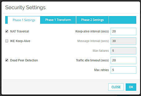
NAT Traversal
Select this check box if you use 1:1 NAT for the connection between devices in the tunnel. NAT Traversal, or UDP Encapsulation, enables traffic to get to the correct destinations.
In the Keep-alive Interval (secs) text box, type the number of seconds that pass before the next NAT keep-alive message is sent.
IKE Keep-alive
Select this check box to enable the Firebox to send messages to its IKE peer to keep the VPN tunnel open.
In the Message Interval (secs) text box, type the number of seconds that pass before the next IKE Keep-alive message is sent.
In the Max failures text box, type the maximum number of times the Firebox tries to send an IKE keep-alive message before it tries to negotiate Phase 1 again.
Dead Peer Detection
Select this check box to enable or disable traffic-based dead peer detection. When you enable dead peer detection, the Firebox connects to a peer only if no traffic is received from the peer for a specified length of time and a packet is waiting to be sent to the peer. This method is more scalable than IKE keep-alive messages.
In the Traffic idle timeout text box, type or select the amount of time (in seconds) that passes before the Firebox tries to connect to the peer.
In the Max retries text box, type or select the number of times the Firebox tries to connect before the peer is declared dead.
Do not enable both IKE Keep-alive and Dead Peer Detection.
Phase 1 Transform
You can configure the Security Settings for the tunnel to configure the transform set the Firebox uses to negotiate the tunnel.
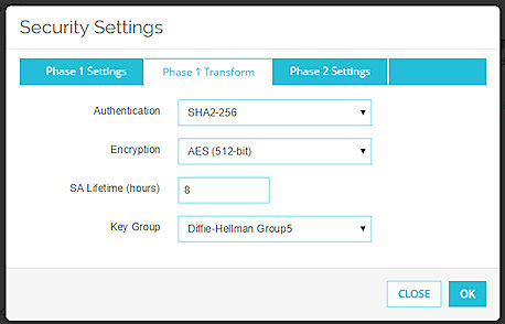
Authentication
Select an authentication method: SHA1, SHA2-256, SHA2-384, or SHA2-512.
Encryption
Select an encryption option: AES (128-bit), AES (192-bit), AES (256-bit), or 3DES.
SA Lifetime (hours)
This is the security association lifetime. Type the number of hours for the SA lifetime. This must be a number smaller than 596,523 hours.
Key Group
Select a Diffie-Hellman group. Options include groups 1, 2, 5, 14, 15, 19, and 20.
Diffie-Hellman groups determine the strength of the master key used in the key exchange process. A higher group number provides greater security, but more time is required to make the keys.
For more information, see About Diffie-Hellman Groups.
Phase 2 Settings
Phase 2 settings include settings for a security association (SA), which defines how data packets are secured when they are passed between two endpoints. The SA keeps all information necessary for the Firebox to know what it should do with the traffic between the endpoints.
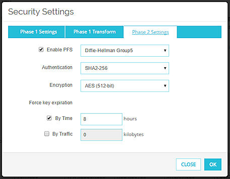
Enable PFS
Select this check box to enable Perfect Forward Secrecy.
Perfect Forward Secrecy gives more protection to keys that are created in a session. Keys made with PFS are not made from a previous key. If a previous key is compromised after a session, your new session keys are secure.
From the drop-down list, select a Diffie-Hellman group. Options include groups 1, 2, 5, 14, 15, 19, and 20.
For more information, go to About Diffie-Hellman Groups.
Authentication
Select an authentication method:
- SHA1
- SHA2-256
- SHA2-384
- SHA2-512
Encryption
Select the encryption method:
- 3DES
- AES (128-bit)
- AES (192-bit)
- AES (256-bit)
The options are listed in order from least secure to most secure.
Force key expiration
Select the check box for the option to use to force the gateway endpoints to generate and exchange new keys after a quantity of time or amount of traffic passes:
- By Time — Type the number of hours after which the keys expire.
- By Traffic — Type the amount of traffic in kilobytes after which the keys expire.
Edit a Spoke Device
From the Hub and Spoke VPN page, you can edit the settings for a spoke device. You can select a spoke device from the Spokes list or from the VPN map.
You cannot change the Firebox that is specified as the spoke device. To use a different Firebox as the spoke device, you must remove the spoke device and add a new spoke device with the correct Firebox.
From the Spokes list:
- Select a spoke device and click Edit.
The Edit Spoke Gateway dialog box appears. - Select a tab to change the configuration settings:
- External Interfaces
- Tunnel Routes
- VPN Options
- Click Save.
The settings for the spoke device are updated.
From the VPN map:
- In the Hub and Spoke VPN map, click a spoke device.
The spoke device dialog box opens.
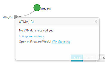
- To change the spoke device VPN settings, click Edit spoke settings.
The Edit Spoke Gateway dialog box opens. - Select a tab to change the configuration settings:
- External Interfaces
- Tunnel Routes
- VPN Options
- Click Save.
The settings for the spoke device are updated.
- In the Hub and Spoke VPN map, click a spoke device.
The spoke device dialog box opens.
- Adjacent to Open in Fireware Web UI, click VPN Statistics.
Fireware Web UI opens for the spoke device with the System Status > VPN Statistics page selected. - Modify the configuration as necessary and save your changes.
Remove a Spoke Device
You can remove a spoke device from the Spokes list. Before you can delete a managed VPN, you must remove all spoke devices from the Hub and Spoke VPN page.
From the Spokes list:
- Select a spoke device and click Remove.
The confirmation message appears. - Click OK.
The spoke device is removed from the managed VPN and all settings related to the managed VPN are removed from the spoke device.
Remove a Managed VPN
Before you can remove a managed VPN, you must first remove all spoke devices from the VPN.
To remove a managed VPN:
- Select Home > VPNs.
The VPNs page opens. - In the VPNs list, select the row of the managed VPN to remove.
- Click Remove.
A confirmation message appears. - Click OK.
The managed VPN is removed and all settings related to the managed VPN are removed from the hub device.