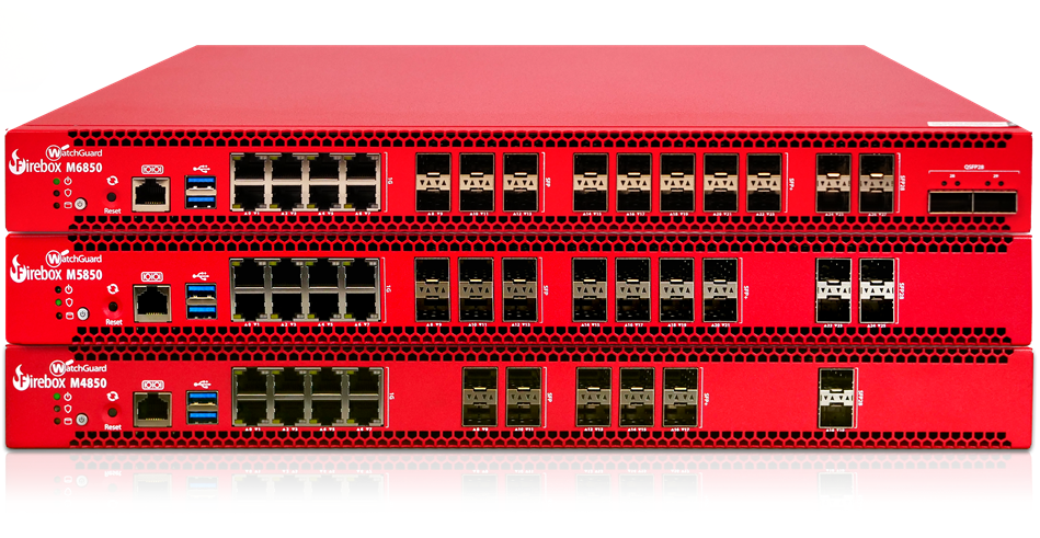
The Firebox High Rackmount M-series represents the next step in the evolution of Firebox, delivering higher performance, greater scalability, and enterprise‑ready reliability, while maintaining the simplicity and consistency of the WatchGuard platform. The Firebox M4850, M5850, and M6850 provide high throughput performance, strong security, flexible port options, and affordability.
Firebox Management in WatchGuard Cloud
You can locally-manage your Firebox with Fireware Web UI or WatchGuard System Manager (WSM), or you can manage your Firebox in WatchGuard Cloud.
WatchGuard Cloud enables you to monitor and configure your WatchGuard products in one place. You can set up your devices and configure and manage security and networking policies across multiple Fireboxes with flexible templates. For Service Providers, a multi-tier architecture makes it easy to manage inventory across your accounts.
- Go to Quick Start — Set Up a New Firebox for information on how to set up your new Firebox.
- If you want to manage your Firebox in WatchGuard Cloud, select Cloud-Managed as the configuration method in the Web Setup Wizard.
- If you want to locally-manage your Firebox, select Locally-Managed as the configuration method in the Web Setup Wizard.
- You can also set up your Firebox directly in WatchGuard Cloud as a new cloud-managed device. When you connect your Firebox to the network and start your new device with factory-default settings, the Firebox automatically connects to WatchGuard Cloud and gets the device configuration. For more information, go to Add a Cloud-Managed Firebox to WatchGuard Cloud.
Fireware
The Firebox runs WatchGuard’s next generation UTM operating system—Fireware. Fireware delivers exceptional protection against today's sophisticated threats to make sure that your business stays connected. For more information on the features of Fireware, go to Firebox Feature Comparison — Locally-Managed and Cloud-Managed.
Upgrade Your Firebox
For the best experience, make sure you upgrade your Firebox to the latest available version of Fireware. To upgrade Fireware, use one of these methods:
- To upgrade a Firebox managed in WatchGuard Cloud, select your Firebox and click Upgrade to firmware <version>. For more information, go to Manage Firmware Versions for Devices in WatchGuard Cloud.
- To upgrade a locally-managed Firebox, in Fireware Web UI, select System > Upgrade OS. For more information, go to Upgrade Fireware or WatchGuard System Manager.
Package Contents
- Firebox device
- Rail installation kit
About Your Hardware
Hardware Specifications
| M4850 | M5850 | M6850 | |
|---|---|---|---|
| Processor | Intel / Granite Rapids-D HCC 12-core (6th Xeon Processor) | Intel / Granite Rapids-D HCC 20-core (6th Xeon Processor) | Intel / Granite Rapids-D HCC 24-core (6th Xeon Processor) |
| Memory | 32 GB 2 x 16 GB DDR5 ECC SODIMM |
32 GB 2 x 16 GB DDR5 ECC SODIMM |
64 GB 2 x 32 GB DDR5 ECC SODIMM |
| Flash Memory |
64 MB QSPI |
64 MB QSPI | 64 MB QSPI |
| Storage | M.2 PCIe SSD 128 GB | M.2 PCIe SSD 128 GB | M.2 PCIe SSD 256 GB |
| Network Interfaces |
8 x 1G RJ45 4 x 1G SFP 6 x 10G SFP+ 2 x 25G SFP28 |
8 x 1G RJ45 6 x 1G SFP 8 x 10G SFP+ 4 x 25G SFP28 |
8 x 1G RJ45 6 x 1G SFP 10 x 10G SFP+ 4 x 25G SFP28 2 x 100G QSFP28 |
| I/O Interfaces |
2 x USB-A 3.2 Gen 1 1 RJ45 Serial Port |
2 x USB-A 3.2 Gen 1 1 RJ45 Serial Port |
2 x USB-A 3.2 Gen 1 1 RJ45 Serial Port |
| Module Bay | OCP3.0 PCIe Gen 5 x8 | OCP3.0 PCIe Gen 5 x8 | OCP3.0 PCIe Gen 5 x8 |
| Power Supply |
2 x hot-swappable |
2 x hot-swappable |
2 x hot-swappable |
| Fans | 4 x 32000 RPM hot-swappable Pulse Width Modulation (PWM) fans | 4 x 32000 RPM hot-swappable Pulse Width Modulation (PWM) fans | 4 x 32000 RPM hot-swappable Pulse Width Modulation (PWM) fans |
| Dimensions |
D = 440 mm (17.32") |
D = 440 mm (17.32") W = 515 mm (20.28") H = 44 mm (1.73") (1U height) |
D = 440 mm (17.32") W = 515 mm (20.28") H = 44 mm (1.73") (1U height) |
| Weight | 9 kg (19.84 lbs) | 9 kg (19.84 lbs) | 9 kg (19.84 lbs) |
| Power Consumption | 374.12 (Max) | 411.56 W (Max) | 506.48 W (Max) |
| Operating Temperature and Humidity |
0° to 40°C (32° to 104°F) 0% to 95% non-condensing |
0° to 40°C (32° to 104°F) 0% to 95% non-condensing |
0° to 40°C (32° to 104°F) 0% to 95% non-condensing |
| Non-Operating Temperature and Humidity |
-10°C to 70°C (14°F to 158°F) 5% to 90% non-condensing |
-10°C to 70°C (14°F to 158°F) 5% to 90% non-condensing |
-10°C to 70°C (14°F to 158°F) 5% to 90% non-condensing |
| Mean-time Between Failures (MTBF) | 417,591 hours | 407,610 hours | 390,055 hours |
TPM (Trusted Platform Module)
This hardware contains a TPM chip for use with secure WatchGuard Cloud registration of the device.
Environmental Requirements
To safely install your Firebox, we recommend that you:
- Install the Firebox indoors.
- Deploy the Firebox in a secure area, such as a locked room, to block the device from people who do not have permission to use it.
- Connect the Firebox to a conditioned power supply to prevent damage from sudden power changes.
- Do not place other devices directly on the Firebox if you have installed the Firebox in a rack.
For installation and additional safety instructions, go to the Sliding Rail Kit Installation Instructions.
Hardware Description
Front View
Power (![]() )
)
The Power indicator is lit to indicate power status.
- Off — Firebox is powered off in standby mode.
- Green — Firebox is powered on.
- Flashing Green — Indicates an issue with one or more redundant power supplies when the power supply is not functioning or disconnected.
Arm/Disarm (![]() )
)
When the device is armed and ready to pass traffic, this indicator is green. When the device is powered on, but not ready to pass traffic, this indicator is red.
Storage (![]() )
)
When there is activity on the storage device, this indicator is yellow.
Power Button
The Power button is lit to indicate power status. It is green when the Firebox is powered on, and red when power is available, but the Firebox is powered off and in standby mode.
Press the power button briefly to turn on the device. The power button will light green when the device is powered on.
To power off the Firebox, press and hold the Power button for at least five seconds until the device powers off and enters standby mode. The Firebox will not power off if you briefly press the Power button.
Reset Button
This button resets the device to factory-default settings. For more information on how to use the reset button, go to Restore Factory-Default Settings.
Serial Console Port (![]() )
)
The RJ45 serial console port enables serial connections to the device. An RJ45 serial cable is not included. For information on how to connect to the Fireware command line interface with the serial port, go to the Fireware CLI Reference Guide available from the Product Documentation web site.
USB Ports (![]() )
)
The device has two USB-A 3.2 Gen 1 ports. You can connect a USB storage device for USB backup and restore or to store a support snapshot. For more information, go to Use a USB Drive for System Backup and Restore.
Each Firebox has several network interfaces. The number and types of interfaces depend on the Firebox model. The Ethernet interfaces have standard RJ45 connectors.
For a list of supported transceivers for SFP+/SFP ports, refer to Supported SFP+/SFP transceivers for Firebox devices.
M4850
- Interfaces 0 to 7 RJ45 support 1 Gbps, 100 Mbps, and 10 Mbps
- Interfaces 8 to 11 SFP support 1 Gbps with compatible SFP transceivers
- Interfaces 12 to 17 SFP+ support 10 Gbps with compatible SFP+/SFP transceivers
- Interfaces 18 to 19 SFP28 support 25 Gbps with compatible SFP28 transceivers
M5850
- Interfaces 0 to 7 RJ45 support 1 Gpbs, 100 Mbps, and 10 Mbps
- Interfaces 8 to 13 SFP support 1 Gbps with compatible SFP transceivers
- Interfaces 14 to 21 SFP+ support 10 Gbps with compatible SFP+/SFP transceivers
- Interfaces 22 to 25 SFP28 support 25 Gbps with compatible SFP28 transceivers
M6850
- Interfaces 0 to 7 RJ45 support 1 Gbps, 100 Mbps, and 10 Mbps
- Interfaces 8 to 13 SFP support 1 Gbps with compatible SFP transceivers
- Interfaces 14 to 23 SFP+ support 10 Gbps with compatible SFP+/SFP transceivers
- Interfaces 24 to 27 SFP28 support 25 Gbps with compatible SFP28 transceivers
- Interfaces 28 to 29 QSFP28 support 100 Gbps with compatible QSFP28 transceivers
There are two status indicators for each interface:
Left indicator (Activity) — The left LED indicator is lit yellow when the link is established, and flashes to indicate network activity. The flashing speed increases as the data sent or received increases.
Right indicator (Connection) —The right LED indicator on the interface indicates the connection status.
1G Interfaces
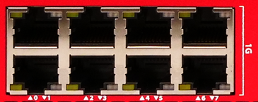
- Yellow — 1000 Mbps
- Green — 100 Mbps
- Not lit — 10 Mbps or no link
1G SFP Interfaces
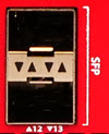
- Yellow — 1 Gbps
- Not Lit — No link
10G SFP+ Interfaces
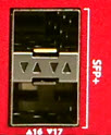
- Yellow — 10 Gbps
- Green — 1 Gbps
- Not Lit — No link
25G SFP28 Interfaces
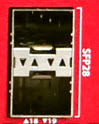
- Yellow — 25 Gbps
- Not Lit — No link
100G QSFP28 Interfaces
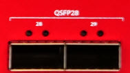
- Yellow — 100 Gbps
- Green — Connected at a lower speed
- Flashing — Activity
- Not Lit — No link
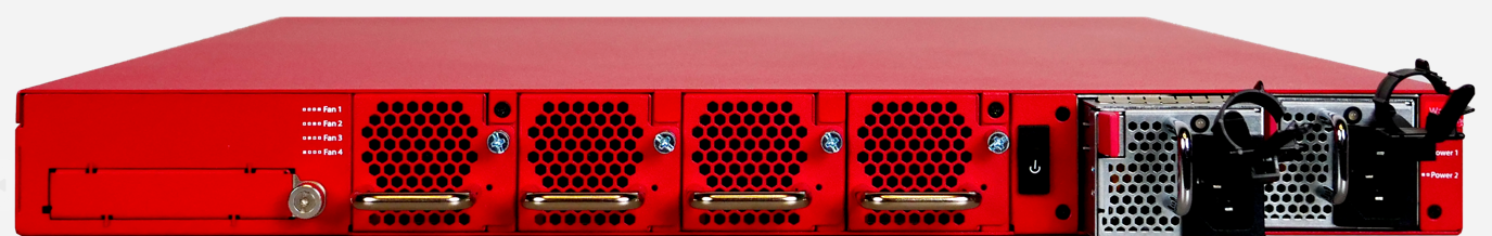
Rear View
OCP 3.0 Network Card Bay
The Firebox has a module bay that supports an optional Open Compute Project (OCP) 3.0 network card. WatchGuard currently offers these network card options:
- 4 port 25G card (SFP28)
- 2 port 100G card (QSFP28)
To insert an OCP network card:
- Make sure the Firebox is powered off.
- Turn the module bay cover screw counter-clockwise to loosen the screw, then remove the cover plate.
You can use a cross-head screwdriver to loosen the screw if it is tight. - Align the network card module with the OCP slot rails.
- Insert the card until it fully seats in the connector.
- Tighten the screw on the OCP network card clockwise to secure into place.
To remove an OCP network card:
- Make sure the Firebox is powered off.
- Turn the screw on the OCP network card counter-clockwise to loosen the screw.
You can use a cross-head screwdriver to loosen the screw if it is tight. - Use the handle on the left side of the OCP network card to carefully pull out the card from the connector.
- Reinstall the cover plate on the module bay.
- Turn the module bay cover screw clockwise to tighten the cover plate into place.
Cooling Fans
The Firebox has four hot-swappable external fans to decrease the internal temperature of the device. The device adjusts the fan speed based on the temperature. If a fan fails, the speed of the fans is adjusted to compensate for optimal cooling.

To replace a fan:
- Turn the screw on the right side of the fan counter-clockwise to loosen the screw.
You can use a cross-head screwdriver to loosen the screw if it is tight. - Use the handle to carefully pull the fan out of the connector.
- Carefully insert the new fan into the fan bay until it firmly seats in the connector.
Make sure the fan is straight and level when you insert the fan. - Turn the screw on the right side of the fan clockwise to tighten the screw.
You can view the current fan speed from the Fireware CLI with the command diagnose hardware system. For more information on how to use the CLI, go to the Fireware Command Line Reference Guide.
Fan Speed (4 Fans – Normal Operation)
Temperature
(CPU Tj)Fan Speed (%) RPM (Approximate) Up to 33° C 35% 11,200 RPM 43° C 45% 14,400 RPM 48° C and higher 60% 19,200 RPM
Fan Speed (3 Fans – After Fan Failure)
Temperature
(CPU Tj)Fan Speed (%) RPM (Approximate) Up to 33° C 55% 17,600 RPM 43° C 70% 22,400 RPM 50° C 90% 28,800 RPM 56° C and higher 100% 32,000 RPM
Power Switch
The rear panel power switch is a one-position rocker switch.

To power on the Firebox from standby mode, press and release the switch briefly to power on the device.
To power off the Firebox, press the switch and hold for 5 seconds or more to power off and enter standby power mode.
When you attach a power cable to one of the power supplies, the system will start up immediately.
In the event of a complete power failure, the Firebox will immediately power off. When power is restored, the Firebox will power on automatically, even if the Firebox was powered off previously.
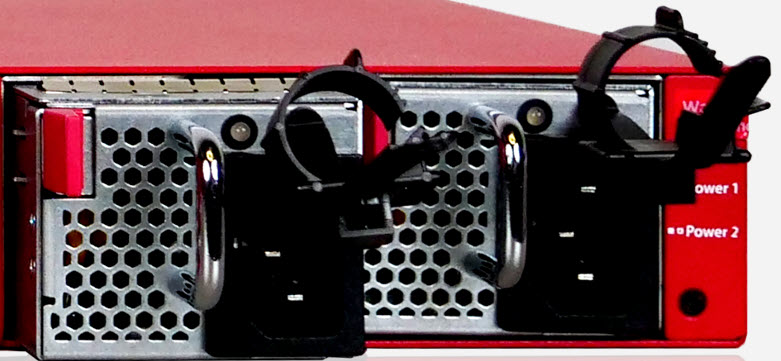
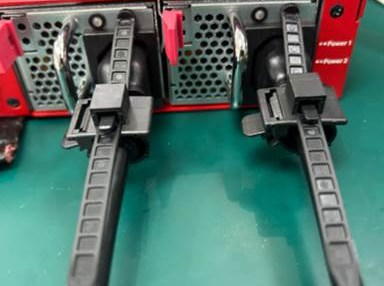
Power Supplies
The Firebox has two redundant hot-swappable power supplies. If a power supply fails or is disconnected:
- The LED indicator on the power supply shows red and an audible alarm sounds.
- The front power button on the Firebox flashes green to indicate a power supply issue.
You can replace the failed power supply while the Firebox is powered by the other power supply.
Power Supply LED Indicator Status Description Green Powered on, normal state Flashing Green Powered off or in standby Red No power or power supply failure
To replace a power supply:
- Use the power indicator to identify the failed power supply. If the device is powered on, the indicator on the failed power supply is red.
- Disconnect the power cable from the power supply you want to replace.
- Find the release tab located on the left side of the power supply.
- Firmly push the release tab to the right with your thumb while you use the power supply handle to pull out the power supply from the slot.
- Carefully slide the replacement power supply into the open slot.
- Press firmly on the face of the power supply until it is flush with the back of the Firebox and it fully connects into place. If the replacement is successful, the power indicator light for the new power supply is green.
Power Supply Alarm
An audible alarm sounds when the power supply fails. You can control the audible alarm of the power supply from the Command Line Interface (CLI) of the Firebox with these commands:
- psubuzzer enable (to enable the audible power supply alarm)
- no psubuzzer enable (to disable the audible power supply alarm)
- show psubuzzer (to show the current status of the power supply alarm)
For more information on how to use the CLI, go to the Fireware Command Line Interface Reference Guide.
Power Cables
The power supplies have a standard power input receptacle for use with an IEC C13 AC power cord (not included). We recommend you use a minimum 18 AWG/10A power cable. WatchGuard offers these regional power cords sold separately for your device:
- WG9033 (US)
- WG9034 (EU)
- WG9035 (UK)
- WG9036 (AU)
- WG9038 (BR)
- WG9039 (JP)
- WG9040 (CH)
Power Cable Retention Straps
Each power supply includes a power cable retention strap to keep the power plug securely inserted and prevent accidental disconnection.
Sliding Rail Kit Installation Instructions
Each Firebox device ships with rail hardware for installation in a four-post network rack. It might require two people to safely complete these steps.
Caution: The included rail kit and ear brackets are intended for installation in four-post network racks. For two-post racks, we recommend you use third-party shelves or heavy-duty rack ears to support the weight of the device in the rack.
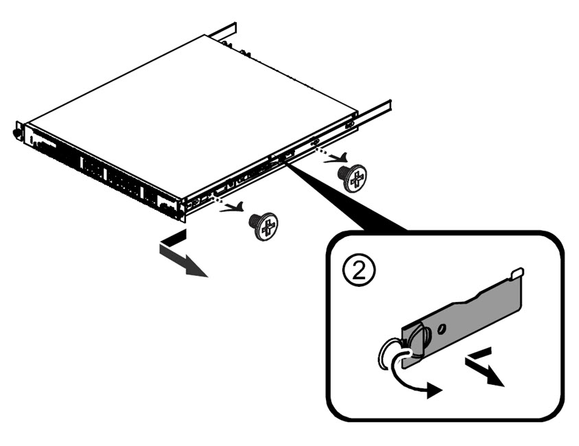
1. Remove the Inner Rails
- Extend the inner rails until they are fully extended.
- Slide the release tab forward to remove the inner rails.
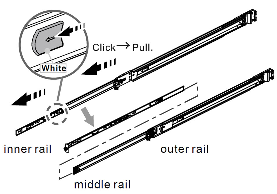
- Push the indicated latch and slide the middle rails backward back into the outer rails.
2. Check the Rack Post Hole Type
Inspect the rack post to determine whether it uses standard 9.5 mm square holes or 7.1 mm round holes.
- If the rack uses standard 9.5 mm square holes, the correct bracket pin is preinstalled, and you can install the slide rail normally.
- If the rack uses 7.1 mm round holes, replace the bracket pin with the correct pin before you install the slide rail.

3. Install the Inner Rail onto the Device
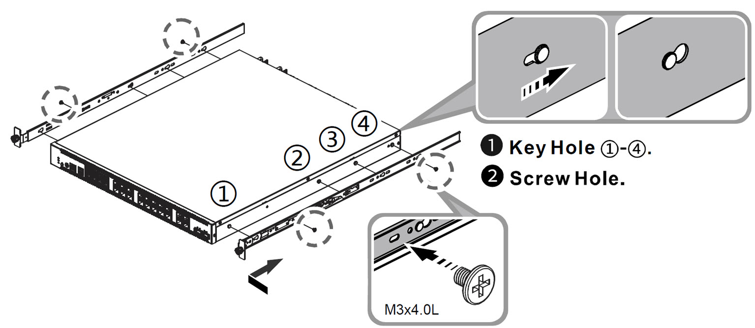
- Align the key holes of the inner rail and the holes on the sides of the device.
- Use the included screws (M3x4.0L) to attach the inner rails to the device with the indicated screw holes.
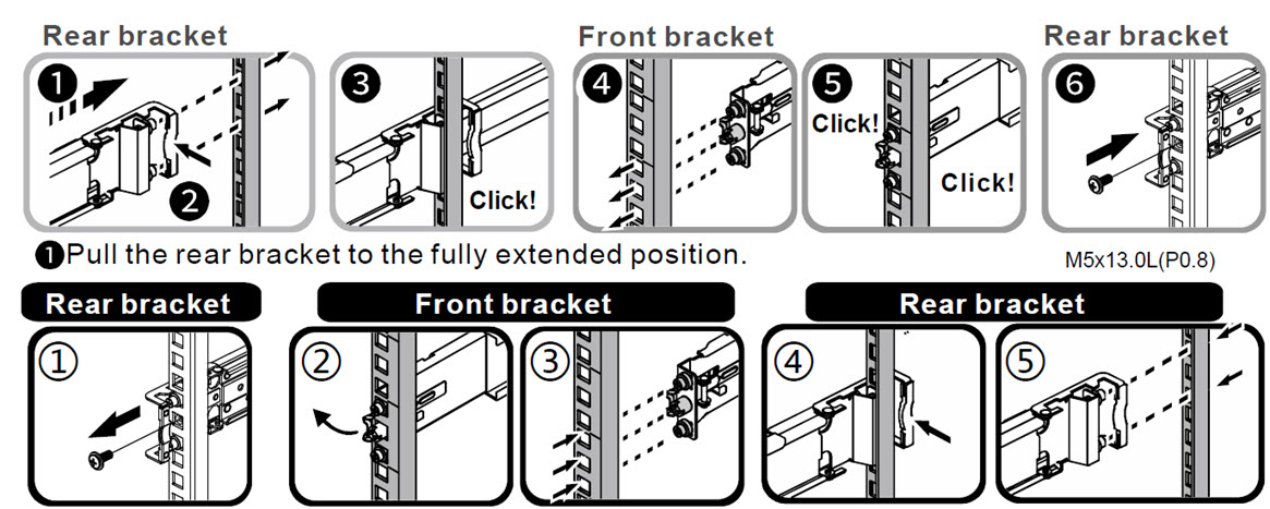
4. Attach the Outer Rail and Bracket Assembly to the Rack Frame
- Position the front and rear brackets on the rack posts.
- Extend the rear bracket to the fully extended position until it clicks into place.
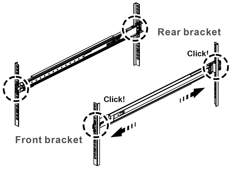
- Ensure both front and rear brackets lock into the rack posts with an audible click.
- Secure the brackets using the appropriate screws (for example, M5×13.0L).
5. Insert the Device into the Rails
- Fully extend the middle rails until they lock, ensuring the ball‑bearing retainer is at the front.
- Make sure you hear an audible click to indicate the rails are locked.
- Align the device (with inner rails installed) horizontally with the middle/outer rails, then slide the device into the rails until it reaches a stop.
- Pull or push the blue release tabs on the inner rails to allow the device to continue sliding inward.
- Secure the device with the included thumb screws.

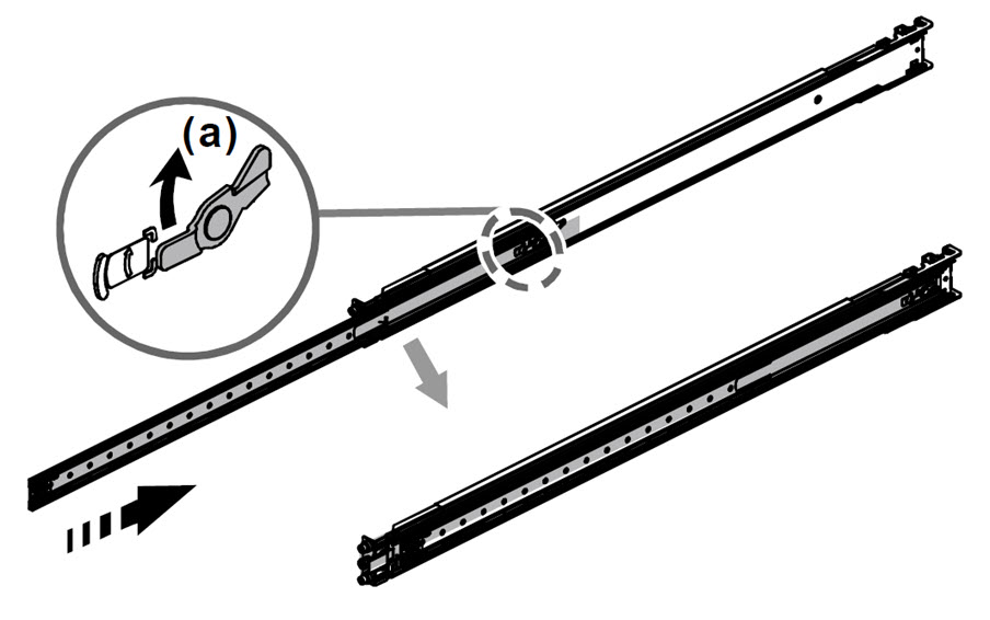
To Remove the Firebox from the Rack (If Required)
- Loosen the thumb screws to allow the device to slide outward.
- Pull the disconnect tab forward at full extension.
- Release the device from the rails.
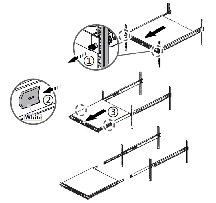
- To remove the inner rails from the device, remove the screws.
- Pull the latch upward to remove the keyhole from the offset on the device.
- Slide the inner rail forward to remove the inner rail.
Precautions
WARNING: Do not place other devices directly on the Firebox, or use the Firebox as a shelf or work space.
When you install the device in a rack, make sure you consider these factors:
Elevated Operating Ambient Temperature
If you install the device in a closed or multi-unit rack assembly, the operating ambient temperature of the rack environment might be greater than room ambient. Make sure the ambient temperature of the rack environment is within the certified operating range specified in this Hardware Guide.
Reduced Air Flow
When you install the device in a rack, make sure that the amount of air flow required for safe operation of the equipment is not compromised.
Mechanical Loading
When you mount the device in the rack, avoid hazardous conditions caused by uneven mechanical loading.
Circuit Overloading
Make sure you connect the device to the power supply circuit in such a way that there is no overloading of the circuits, and no impact on overcurrent protection and supply wiring.
Reliable Grounding
Make sure all rack-mounted equipment is correctly grounded. For example, make sure you use power strips instead of direct connections to the branch circuit.
Restore Factory-Default Settings
If you have a problem in your configuration file that you cannot correct, or you cannot access the device, you can restore the device to factory-default settings and start with a new configuration. For example, if you do not know the administrator account passphrase, or if a power interruption causes damage to the Fireware operating system, you can restore the Firebox to the factory-default settings and build your configuration again.
To reset your device:
- If necessary, use the power switch on the rear of the device to power it on.
- Press and hold the Power button on the front of the device for five seconds to power it off.
- Press and hold the Reset button, while you briefly press the Power button on the front of the device to power it on.
- Continue to hold the Reset button while the Arm indicator is red.
- Continue to hold the Reset button while the Arm indicator is slowly flashing green.
- When the Arm indicator flashes green more rapidly, release the Reset button.
- Wait until the Arm indicator starts flashing red.
- Press and hold the Power button on the front of the device for five seconds to power off the device.
- Briefly press the Power button on the front of the device to power it on.
Notices
All WatchGuard products are designed and tested to meet strict safety requirements. These requirements include product safety approvals and other global compliance standards. Please read these instructions carefully before operating the product, and refer to them as needed to ensure the continued safe operation of your product.
For security, privacy, legal compliance, certifications, and environmental information, visit the WatchGuard Trust Center.
Safety Warning
- The WatchGuard power cord is dedicated for
Firebox T185/M295/M395/M495/M595/M695/M4850/M5850/M6850 models and cannot be used for other devices.
本ACコードはT185/M295/M395/M495/M595/M695/M4850/M5850/M6850モデル専用です。他の機器には使用しないでください。 - Do not place objects on the power cord.
- Do not obstruct the ventilation openings. These openings prevent overheating of the machine.
- Never push objects of any kind into slots or openings on this equipment. Making a contact with a voltage point or shorting out a part may result in fire or electrical shock.
- When removing or installing an appliance, follow the general installation safety instructions.
- You must disconnect the AC power cord from the Firebox before you remove the cover of the Firebox for any reason.
- There is risk of explosion if the battery is replaced by an incorrect type. Dispose of used batteries according to the manufacturer’s instructions.
警示 本電池如果更換不正確會有爆炸的危險,請勿自行更換電池。 - Class I Equipment. This equipment must be earthed. The power plug must be connected to a properly wired earth ground socket outlet. An improperly wired socket outlet could place hazardous voltages on accessible metal parts.
- All Ethernet cables are designed for intra-building connection to other equipment. Do not connect these ports directly to communication wiring or other wiring that exits the building where the appliance is located.
- Disconnect the power source prior to defeating or bypassing the equipment protection means (like enclosure), and to restore the equipment protection means before restoring power.
Disclaimer
WatchGuard shall not be held liable if the end user alters, modifies, or repairs any WatchGuard hardware appliance.
Avis
Tous les produits WatchGuard sont conçus et testés pour répondre à des exigences strictes en matière de sécurité. Ces exigences comprennent les homologations de sécurité des produits ainsi que d’autres normes de conformité internationales. Veuillez lire attentivement ces instructions avant d’utiliser le produit et vous y référer au besoin afin d’assurer le fonctionnement sûr et continu de votre produit.
Pour des informations sur la sécurité, la confidentialité, la conformité légale, les certifications et l’environnement, consultez le WatchGuard Trust Center.
Remarques sur la sécurité
- Le cordon d'alimentation secteur est uniquement destiné aux produits WatchGuard et ne peut pas être utilisé pour d'autres équipements.
- Ne placez pas d'objets sur le cordon d'alimentation.
- Ne pas obstruer les ouvertures de ventilation. Ces ouvertures évitent la surchauffe de la machine.
- N'introduisez jamais d'objets d'aucune sorte dans les fentes ou les ouvertures de cet équipement. Établir un contact avec un point de tension ou court-circuiter une pièce peut entraîner un incendie ou un choc électrique.
- Lors de la dépose ou de l'installation d'un appareil, respectez les consignes générales de sécurité d'installation.
- Vous devez débrancher le cordon d'alimentation CA du Firebox avant de retirer le couvercle du Firebox pour quelque raison que ce soit.
- Il y a un risque d'explosion si la batterie est remplacée par un type incorrect. Jetez les piles usagées conformément aux instructions du fabricant.
- Équipement de classe I. Cet équipement doit être mis à la terre. La fiche d’alimentation doit être branchée à une prise correctement câblée avec mise à la terre. Une prise mal câblée pourrait appliquer des tensions dangereuses sur les parties métalliques accessibles.
- Tous les câbles Ethernet sont conçus pour un raccordement à l’intérieur d’un bâtiment à d’autres équipements. Ne connectez pas ces ports directement à du câblage de communication ou à tout autre câblage qui sort du bâtiment où l’appareil est installé.
- Débranchez la source d’alimentation avant de neutraliser ou de contourner les dispositifs de protection de l’équipement (comme le boîtier), et rétablissez ces dispositifs de protection avant de rebrancher l’alimentation.
Clause de non-responsabilité
WatchGuard décline toute responsabilité si l'utilisateur final altère, modifie ou répare tout appareil matériel WatchGuard.
Hinweise Zur Sicherheit
Alle WatchGuard-Produkte werden entwickelt und getestet, um strenge Sicherheitsanforderungen zu erfüllen. Diese Anforderungen umfassen Sicherheitszertifizierungen für Produkte sowie weitere internationale Compliance-Standards. Bitte lesen Sie diese Anweisungen sorgfältig durch, bevor Sie das Produkt in Betrieb nehmen, und ziehen Sie sie bei Bedarf heran, um den sicheren und dauerhaften Betrieb Ihres Produkts zu gewährleisten.
Informationen zu Sicherheit, Datenschutz, rechtlicher Compliance, Zertifizierungen und Umwelt finden Sie im WatchGuard Trust Center.
Sicherheitshinweis
- Das Netzkabel ist nur für WatchGuard-Produkte und nicht für andere Geräte geeignet.
- Legen Sie keine Gegenstände auf das Netzkabel.
- Verdecken Sie nicht die Lüftungsöffnungen. Diese Öffnungen verhindern eine Überhitzung der Maschine.
- Stecken Sie niemals Gegenstände jeglicher Art in die Schlitze oder Öffnungen des Geräts stecken. Der Kontakt mit einem spannungsführenden Punkt oder das Kurzschließen eines Bauteils kann zu einem Brand oder elektrischen Schlag führen.
- Beim Entfernen oder Installieren eines Gerätes, nach den allgemeinen Installation Sicherheitshinweise.
- Sie müssen das Netzkabel von der Firebox trennen, bevor Sie die Abdeckung der Firebox aus irgendeinem Grund entfernen.
- Es besteht Explosionsgefahr, wenn die Batterie durch einen falschen Typ ersetzt wird. Entsorgen Sie gebrauchte Batterien gemäß den Anweisungen des Herstellers.
- Gerät der Klasse I. Dieses Gerät muss geerdet werden. Der Netzstecker muss an eine ordnungsgemäß verdrahtete Steckdose mit Schutzerdung angeschlossen werden. Eine falsch verdrahtete Steckdose kann gefährliche Spannungen an zugänglichen Metallteilen verursachen.
- Alle Ethernet-Kabel sind für die Verbindung innerhalb eines Gebäudes mit anderen Geräten ausgelegt. Schließen Sie diese Ports nicht direkt an Kommunikationsleitungen oder andere Verkabelungen an, die das Gebäude verlassen, in dem sich das Gerät befindet.
- Trennen Sie die Stromversorgung, bevor Sie Schutzvorrichtungen des Geräts (z. B. das Gehäuse) außer Kraft setzen oder umgehen, und stellen Sie sicher, dass diese Schutzvorrichtungen wieder aktiviert sind, bevor Sie die Stromversorgung wiederherstellen.
Haftungsausschluss
WatchGuard haftet nicht, wenn der Endbenutzer eine Hardware-Appliance von WatchGuard ändert, modifiziert oder repariert.
Avisos
Todos os produtos WatchGuard são projetados e testados para atender a requisitos rigorosos de segurança. Esses requisitos incluem certificações de segurança de produtos e outras normas globais de conformidade. Leia atentamente estas instruções antes de operar o produto e consulte-as sempre que necessário para garantir a operação segura e contínua do seu produto.
Para informações sobre segurança, privacidade, conformidade legal, certificações e meio ambiente, visite o WatchGuard Trust Center.
Aviso de Segurança
- O cabo de alimentação WatchGuard é dedicado aos modelos Firebox T185/M295/M395/M495/M595/M695/M4850/M5850/M6850 e não pode ser usado com outros dispositivos.
- Não coloque objetos sobre o cabo de alimentação.
- Não obstrua as aberturas de ventilação. Essas aberturas evitam o superaquecimento do equipamento.
- Nunca insira objetos de qualquer tipo nas aberturas ou fendas deste equipamento. O contato com pontos de tensão ou curto-circuito de componentes pode resultar em incêndio ou choque elétrico.
- Ao remover ou instalar um equipamento, siga as instruções gerais de segurança de instalação.
- Você deve desconectar o cabo de alimentação CA do Firebox antes de remover a tampa por qualquer motivo.
- Há risco de explosão se a bateria for substituída por um tipo incorreto. Descarte as baterias usadas de acordo com as instruções do fabricante.
- Equipamento de Classe I. Este equipamento deve ser aterrado. O plugue de alimentação deve ser conectado a uma tomada devidamente aterrada. Uma tomada mal conectada pode colocar tensões perigosas nas partes metálicas acessíveis.
- Todos os cabos Ethernet são projetados para conexão interna ao edifício com outros equipamentos. Não conecte essas portas diretamente a fiações de comunicação ou outras fiações que saiam do edifício onde o equipamento está localizado.
- Desconecte a fonte de energia antes de desativar ou contornar os meios de proteção do equipamento (como o gabinete) e restaure esses meios de proteção antes de restabelecer a energia.
Isenção de Responsabilidade
A WatchGuard não se responsabiliza caso o usuário final altere, modifique ou repare qualquer equipamento de hardware da WatchGuard.
Avisos
Todos los productos WatchGuard están diseñados y probados para cumplir con estrictos requisitos de seguridad. Estos requisitos incluyen certificaciones de seguridad del producto y otras normas globales de cumplimiento. Lea atentamente estas instrucciones antes de operar el producto y consúltelas cuando sea necesario para garantizar el funcionamiento seguro y continuo de su producto.
Para información sobre seguridad, privacidad, cumplimiento legal, certificaciones y medio ambiente, visite el WatchGuard Trust Center.
Aviso de seguridad
- El cable de alimentación de WatchGuard está diseñado específicamente para los modelos Firebox T185/M295/M395/M495/M595/M695/M4850/M5850/M6850 y no debe utilizarse con otros dispositivos.
- No coloque objetos sobre el cable de alimentación.
- No obstruya las aberturas de ventilación. Estas aberturas evitan el sobrecalentamiento del equipo.
- Nunca introduzca objetos de ningún tipo en las ranuras o aberturas de este equipo. El contacto con puntos de voltaje o el cortocircuito de componentes puede provocar incendios o descargas eléctricas.
- Al retirar o instalar un equipo, siga las instrucciones generales de seguridad de instalación.
- Debe desconectar el cable de alimentación de CA del Firebox antes de retirar la cubierta por cualquier motivo.
- Existe riesgo de explosión si la batería se reemplaza por un tipo incorrecto. Deseche las baterías usadas de acuerdo con las instrucciones del fabricante.
- Equipo de Clase I. Este equipo debe estar conectado a tierra. El enchufe de alimentación debe conectarse a una toma de corriente con conexión a tierra adecuada. Una toma mal cableada puede generar voltajes peligrosos en partes metálicas accesibles.
- Todos los cables Ethernet están diseñados para conexiones dentro del edificio con otros equipos. No conecte estos puertos directamente a cableado de comunicaciones u otro cableado que salga del edificio donde se encuentra el equipo.
- Desconecte la fuente de alimentación antes de anular o eludir los mecanismos de protección del equipo (como la carcasa), y restablezca dichos mecanismos antes de volver a conectar la alimentación.
Descargo de responsabilidad
WatchGuard no se hace responsable si el usuario final altera, modifica o repara cualquier equipo de hardware de WatchGuard.
FCC (USA)
This device complies with part 15 of the FCC Rules. Operation is subject to the following two conditions: (1) This device may not cause harmful interference, and (2) this device must accept any interference received, including interference that may cause undesired operation.
This equipment has been tested and found to comply with the limits for a Class B digital device, pursuant to part 15 of the FCC Rules. These limits are designed to provide reasonable protection against harmful interference in a residential installation.
This equipment generates, uses and can radiate radio frequency energy and, if not installed and used in accordance with the instructions, may cause harmful interference to radio communications. However, there is no guarantee that interference will not occur in a particular installation. If this equipment does cause harmful interference to radio or television reception, which can be determined by turning the equipment off and on, the user is encouraged to try to correct the interference by one or more of the following measures:
- Reorient or relocate the receiving antenna.
- Increase the separation between the equipment and receiver.
- Connect the equipment into an outlet on a circuit different from that to which the receiver is connected.
- Consult the dealer or an experienced radio/TV technician for help.
FCC Caution:
Any changes or modifications not expressly approved by the party responsible for compliance could void the user’s authority to operate this equipment.
This transmitter must not be co-located or operating in conjunction with any other antenna or transmitter.
Operations in the 5.15-5.25 GHz band are restricted to indoor usage only.
This device meets all the other requirements specified in Part 15E, Section 15.407 of the FCC Rules.
Radiation Exposure Statement:
This equipment complies with FCC radiation exposure limits set forth for an uncontrolled environment. This equipment should be installed and operated with minimum distance of 20cm between the radiator & your body.
ISED / IC (Canada)
This device complies with ISED’s licence-exempt RSSs. Operation is subject to the following two conditions: (1) This device may not cause harmful interference, and (2) this device must accept any interference received, including interference that may cause undesired operation.
Le présent appareil est conforme aux CNR d’ ISED applicables aux appareils radio exempts de licence. L’exploitation est autorisée aux deux conditions suivantes: (1) le dispositif ne doit pas produire de brouillage préjudiciable, et (2) ce dispositif doit accepter tout brouillage reçu, y compris un brouillage susceptible de provoquer un fonctionnement indésirable.
Caution
(i) the device for operation in the band 5150-5250 MHz is only for indoor use to reduce the potential for harmful interference to co-channel mobile satellite systems;
(ii) where applicable, antenna type(s), antenna models(s), and worst-case tilt angle(s) necessary to remain compliant with the e.i.r.p. elevation mask requirement set forth in section 6.2.2.3 shall be clearly indicated.
Avertissement
Le guide d’utilisation des dispositifs pour réseaux locaux doit inclure des instructions précises sur les restrictions susmentionnées, notamment :
(i) les dispositifs fonctionnant dans la bande 5150-5250 MHz sont réservés uniquement pour une utilisation à l’intérieur afin de réduire les risques de brouillage préjudiciable aux systèmes de satellites mobiles utilisant les mêmes canaux;
(ii) lorsqu’il y a lieu, les types d’antennes (s’il y en a plusieurs), les numéros de modèle de l’antenne et les pires angles d’inclinaison nécessaires pour rester conforme à l’exigence de la p.i.r.e. applicable au masque d’élévation, énoncée à la section 6.2.2.3, doivent être clairement indiqués.
Radiation Exposure Statement
This equipment complies with ISED radiation exposure limits set forth for an uncontrolled environment. This equipment should be installed and operated with minimum distance 20cm between the radiator & your body.
Déclaration d'exposition aux radiations
Cet équipement est conforme aux limites d'exposition aux rayonnements ISED établies pour un environnement non contrôlé. Cet équipement doit être installé et utilisé avec un minimum de 20cm de distance entre la source de rayonnement et votre corps.
For indoor use only. Pour une utilisation en intérieur uniquement.
UKCA (United Kingdom)
This device is in conformity with the relevant legislation of the United Kingdom. To view the full UK Declaration of Conformity for this device, go to the WatchGuard Trust Center at www.watchguard.com/wgrd-trust-center/declarations-conformity.
UK Regulation(s):
- Electrical Equipment (Safety) Regulations 2016 (SI 2016/1101)
- Electromagnetic Compatibility Regulations 2016 (SI 2016/1091)
- Restriction of the Use of Certain Hazardous Substances in Electrical and Electronic Equipment Regulations 2012 (SI 2012/3032)
Common Standards:
- IEC 62368-1:2018
- BS EN 55032:2015+A11:2020+A1:2020
- CISPR 32:2015+AMD1:2019
- VCCI-CISPR 32:2016
- AS/NZS CISPR 32:2015/AMD1:2020
- BS EN 55035:2017+A11:2020
- BS EN IEC 61000-3-2:2019+A1:2021+A2:2024
- BS EN 61000-3-3:2013+A1:2019+A2:2021
- IEC 61000-4-2 Edition 3.0 2025-03
- IEC 61000-4-3 Edition 4.0 2020-09
- IEC 61000-4-4 Edition 3.0 2012-04
- IEC 61000-4-5 Edition 3.1 2017-08
- IEC 61000-4-6 Edition 5.0 2023-06
- IEC 61000-4-8 Edition 2.0 2009-09
- IEC 61000-4-11 Edition 3.0 2020-01
The products identified above comply with the requirements for UKCA marking.
Additional Compliance:
- FCC Part 15B
- ICES-003 Issue 7
CE (European Union)
This device is in conformity with the relevant legislation of the European Union. To view the full EU Declaration of Conformity for this device, go to the WatchGuard Trust Center at www.watchguard.com/wgrd-trust-center/declarations-conformity.
EU Directive(s):
- Low Voltage (2014/35/EU)
- Electromagnetic Compatibility (2014/30/EU)
- RoHS (2002/95/EC)
- WEEE Directive 2002/96/EC
- REACH EC 1907/2006
Common Standards:
- IEC 62368-1:2018
- EN 55032:2015/A11:2020
- FCC Part 15B
- ICES-003 issue7
- CISPR 32:2015+AMD1:2019
- VCCI-CISPR 32:2016
- AS/NZS CISPR 32:2015/AMD1:2020
- EN 55035:2017/A11:2020
- EN IEC 61000-3-2:2019+A1:2021+A2:2024
- EN 61000-3-3:2013+A1:2019+A2:2021
- IEC 61000-4-2 Edition 3.0 2025-03
- IEC 61000-4-3 Edition 4.0 2020-09
- IEC 61000-4-4 Edition 3.0 2012-04
- IEC 61000-4-5 Edition 3.1 2017-08
- IEC 61000-4-6 Edition 5.0 2023-06
- IEC 61000-4-8 Edition 2.0 2009-09
- IEC 61000-4-11 Edition 3.0 2020-01
- BS EN 55032:2015+A11:2020+A1:2020
- BS EN 55035:2017+A11:2020
RoHS Statement
The Restriction of Hazardous Substances 2.0 (RoHS 2.0) in Electrical and Electronic Equipment Directive was passed into law by the European Union (EU). It affects manufacturers, sellers, distributors and recyclers of electrical and electronic equipment containing lead, cadmium, mercury, hexavalent chrome, polybrominated diphenylether (PBDE), polybrominated biphenyl (PBB), Bis (2-ethylhexyl) phthalate (DEHP), Butyl benzyl phthalate (BBP), Dibutyl phthalate (DBP) and Diisobutyl phthalate (DIBP). After June 4, 2015 the use of these materials are banned in new products sold in Europe.
WatchGuard declares that all products listed herein comply with European Union RoHS Directive (RoHS 2.0 2011/65/EU and 2015/863/EU) requirements taking the following Annex III exemptions: [stating the list of exemptions, 6(c) ,7(a) ,7(C)-1].
Access Points: AP130, AP140, AP230W, AP330, AP340, AP332CR, AP430CR, AP432, AP440
Firebox: N5V, T25, T25-W, T45, T45-PoE, T45-W-PoE, T45-CW, T85-PoE, T115-W, T125, T125-W, T145, T145-W, T185, M290, M295, M390, M395, M495, M590, M595, M690, M695, M4850, M5850, M6850
| Substances Listed | Limit |
|---|---|
| Cadmium(Cd) | ≤ 0.01% (100 ppm) |
| Hexa‐valent Chromium (Cr6+) | ≤ 0.1% (1000 ppm) |
| Lead (Pb) | ≤ 0.1% (1000 ppm) * |
| Mercury (Hg) | ≤ 0.1% (1000 ppm) |
| Polybrominated biphenyis (PBB) | ≤ 0.1% (1000 ppm) |
| Polybrominated diphenylethers (PBDE or PBBE) | ≤ 0.1% (1000 ppm) |
| Bis (2-ethylhexyl) phthalate (DEHP) | ≤ 0.1% (1000 ppm) |
| Butyl benzyl phthalate (BBP) | ≤ 0.1% (1000 ppm) |
| Dibutyl phthalate (DBP) | ≤ 0.1% (1000 ppm) |
| Diisobutyl phthalate (DIBP) | ≤ 0.1% (1000 ppm) |
* (contains Lead > 0.1% by weight because of exempted applications)
7a lead in high melting temperature type solders (i.e. lead based alloys containing 85 % by weight or more lead)
7(c) I. Electrical and electronic components containing lead in a glass or ceramic other than dielectric ceramic in capacitors, e.g. piezo electronic devices, or in a glass or ceramic matrix compound.
WEEE Statement
WatchGuard asks that all our products to be recycled at the end of their current use to comply with local waste compliance requirements.
WatchGuard supports the EU Waste Electrical and Electronic Equipment (WEEE) Directive (2012/19/EU). That means that WEEE may not be disposed as unsorted municipal waste but is to be collected separately.
WatchGuard products are therefore labeled with this symbol:
The WEEE symbol on your WatchGuard equipment indicates that it should not be disposed of by the end user with unsorted municipal waste, but in a manner consistent with required EU Directives, and the local transposition of the Directive in the end user's jurisdiction. The symbol is placed per CENELEC standard EN50419.
WEEE may contain hazardous substances which may negatively affect the environment and human health when disposed of through normal channels. Batteries that are not enclosed in the waste equipment must be separated from it and disposed of separately before being handed in at a collection point. Old batteries, and in certain cases also the waste equipment, can likewise be returned free of charge to the point of sale. You are responsible for deleting any personal data on the waste equipment. WatchGuard is committed to reduce the negative environmental and human health effects of WEEE which will help prevent potential negative consequences for the environment and human health. If you are a consumer please use your local recycling option. This is usually your municipal refuse site.
Japan VCCI Notice (Class A ITE)
これはVCCI評議会の基準に基づくクラスA製品です。本製品がラジオやテレビ受信機の近くで使用され
ている場合は、電波障害を引き起こすことがあります。インストールして、取扱説明書に従って
機器を使用しています VCCI-A
China Class A Notice
警告:未避免電磁干擾,本產品不應安裝或使用於住宅環境。
Taiwan RoHS

Taiwan Class A Notice
警告使用者:這是甲類產品,應使用並正確安裝。本產品可能會造成無線電干擾,在這種情況下,用
戶可能需要採取適當的措施。
警示 本電池如果更換不正確會有爆炸的危險,請勿自行更換電池
Taiwan NCC
低功率電波輻射性電機管理辦法
第十二條 經型式認證合格之低功率射頻電機 , 非經許可 , 公司﹑商號或使用者均不得擅自變更頻率﹑
加大功率或變更原設計之特性及功能。
第十四條 低功率射頻電機之使用不得影響飛航安全及干擾合法通信;經發現有干擾現象時 , 應立即停
用 , 並改善至無干擾時方得繼續使用。前項合法通信 , 指依電信法規定作業之無線電通信。 低功率射
頻電機須忍受合法通信或工業、科學及醫療用電波輻射性電機設備之干擾。
電磁波曝露量MPE標準值(MPE) 1mW/cm2,送測產品實值為0.338 mW/cm2
無線資訊傳輸設備避免影響附近雷達系統之操作
Taiwan BSMI CNS 15936 Type A Notice
警告:為避免電磁干擾,本產品不應安裝或使用於住宅環境。
Brazil Notice
Este equipamento não tem direito à proteção contra interferência prejudicial e não pode causar interferência em sistemas devidamente autorizados.
Mexico Notice
La operación de este equipo está sujeta a las siguientes dos condiciones:
(i) es posible que este equipo o dispositivo no cause interferencia perjudicial y
(ii) este equipo o dispositivo debe aceptar cualquier interferencia, incluyendo la que pueda causar su operación no deseada.
Limited Hardware Warranty
This Limited Hardware Warranty (the “Warranty”) applies to the enclosed hardware product, not including any associated software, which is licensed pursuant to a separate end-user license agreement and warranty (the “Product”). BY USING THE PRODUCT, YOU (either an individual or a single entity) AGREE TO THE TERMS HEREOF.
If you do not agree to these terms, please return this package, along with proof of purchase, to the authorized dealer from which you purchased it for a full refund. WatchGuard Technologies, Inc. (“WatchGuard”) and you agree as set forth below or on the reverse side of this card, as applicable.
- LIMITED WARRANTY. WatchGuard warrants that upon delivery and for one (1) year thereafter (the “Warranty Period”): (a) the Product will be free from material defects in materials and workmanship, and (b) the Product, when properly installed and used for its intended purpose and in its intended operating environment, will perform substantially in accordance with WatchGuard applicable specifications.
This warranty does not apply to any Product that has been: (i) altered, repaired or modified by any party other than WatchGuard except for the replacement or inclusion of specified components authorized in, and performed in strict accordance with, documentation provided by WatchGuard; or (ii) damaged or destroyed by force majeure events, accidents, power spikes or similar events or by any intentional, reckless or negligent acts or omissions of any party. You may have additional warranties with respect to the Product from the manufacturers of Product components. However, you agree not to look to WatchGuard for, and hereby release WatchGuard from any liability for, performance of, enforcement of, or damages or other relief on account of, any such warranties or any breach thereof.
- REMEDIES. If any Product does not comply with the WatchGuard warranties set forth in Section 1 above, WatchGuard will, following the receipt of the product you claim is defective and at its option, either (a) repair the Product, or (b) replace the Product with a like or similar product; provided, that you will be responsible for returning the Product and for all costs of shipping and handling. Repair or replacement of the Product shall not extend the Warranty Period. Any Product, component, part or other item replaced by WatchGuard becomes the property of WatchGuard. WatchGuard shall not be responsible for return of or damage to any software, firmware, information or data contained in, stored on, or integrated with any returned Products.
- DISCLAIMER AND RELEASE. THE WARRANTIES, OBLIGATIONS AND LIABILITIES OF WATCHGUARD, AND YOUR REMEDIES, SET FORTH IN PARAGRAPHS 1 AND 2 ABOVE ARE EXCLUSIVE AND IN SUBSTITUTION FOR, AND YOU HEREBY WAIVE, DISCLAIM AND RELEASE ANY AND ALL OTHER WARRANTIES, OBLIGATIONS AND LIABILITIES OF WATCHGUARD AND ALL OTHER RIGHTS, CLAIMS AND REMEDIES YOU MAY HAVE AGAINST WATCHGUARD, EXPRESS OR IMPLIED, ARISING BY LAW OR OTHERWISE, WITH RESPECT TO ANY NONCONFORMANCE OR DEFECT IN THE PRODUCT (INCLUDING, BUT NOT LIMITED TO, ANY IMPLIED WARRANTY OF MERCHANTABILITY OR FITNESS FOR A PARTICULAR PURPOSE, ANY IMPLIED WARRANTY ARISING FROM COURSE OF PERFORMANCE, COURSE OF DEALING, OR USAGE OF TRADE, ANY WARRANTY O NONINFRINGEMENT, ANY WARRANTY OF UNINTERRUPTED OR ERROR-FREE OPERATION, ANY OBLIGATION, LIABILITY, RIGHT, CLAIM OR REMEDY IN TORT, WHETHER OR NOT ARISING FROM THE NEGLIGENCE (WHETHER ACTIVE, PASSIVE OR IMPUTED) OR FAULT OF WATCHGUARD OR FROM PRODUCT LIABILITY, STRICT LIABILITY OR OTHER THEORY, AND ANY OBLIGATION, LIABILITY, RIGHT, CLAIM OR REMEDY FOR LOSS OR DAMAGE TO, OR CAUSED BY OR CONTRIBUTED TO BY, THE PRODUCT).
- LIMITATION AND LIABILITY. WATCHGUARD’S LIABILITY (WHETHER ARISING IN CONTRACT (INCLUDING WARRANTY), TORT (INCLUDING ACTIVE, PASSIVE OR IMPUTED NEGLIGENCE AND STRICT LIABILITY AND FAULT) OR OTHER THEORY) WITH REGARD TO ANY PRODUCT WILL IN NO EVENT EXCEED THE PURCHASE PRICE PAID BY YOU FOR SUCH PRODUCT. THIS SHALL BE TRUE EVEN IN THE EVENT OF THE FAILURE OF ANY AGREED REMEDY. IN NO EVENT WILL WATCHGUARD BE LIABLE TO YOU OR ANY THIRD PARTY (WHETHER ARISING IN CONTRACT (INCLUDING WARRANTY), TORT (INCLUDING ACTIVE, PASSIVE OR IMPUTED NEGLIGENCE AND STRICT LIABILITY AND FAULT) OR OTHER THEORY) FOR COST OF COVER OR FOR ANY INDIRECT, SPECIAL, INCIDENTAL, OR CONSEQUENTIAL DAMAGES (INCLUDING WITHOUT LIMITATION LOSS OF PROFITS, BUSINESS, OR DATA) ARISING OUT OF OR IN CONNECTION WITH THIS WARRANTY OR THE USE OF OR INABILITY TO USE THE PRODUCT, EVEN IF WATCHGUARD HAS BEEN ADVISED OF THE POSSIBILITY OF SUCH DAMAGES. THIS SHALL BE TRUE EVEN IN THE EVENT OF THE FAILURE OF ANY AGREED REMEDY.
- MISCELLANEOUS PROVISIONS. This Warranty will be governed by the laws of the state of Washington, U.S.A., without reference to its choice of law rules. The provisions of the 1980 United Nations Convention on Contracts for the International Sales of Goods, as amended, shall not apply. You agree not to directly or indirectly transfer the Product or use of the product or associated documentation to any country to which such transfer would be prohibited by the U.S. Export laws and regulations. If any provision of this Warranty is found to be invalid or unenforceable, then the remainder shall have full force and effect and the invalid provision shall be modified or partially enforced to the maximum extent permitted by law to effectuate the purpose of this Warranty. This is the entire agreement between WatchGuard and you relating to the Product, and supersedes any prior purchase order, communications, advertising or representations concerning the Product AND BY USING THE PRODUCT YOU AGREE TO THESE TERMS. IF THE PRODUCT IS BEING USED BY AN ENTITY, THE INDIVIDUAL INDICATING AGREEMENT TO THESE TERMS BY USING THE PRODUCT REPRESENTS AND WARRANTS THAT (A) SUCH INDIVIDUAL IS DULY AUTHORIZED TO ACCEPT THE WARRANTY ON BEHALF OF THE ENTITY AND TO BIND THE ENTITY TO THE TERMS OF THIS WARRANTY; (B) THE ENTITY HAS THE FULL POWER, CORPORATE OR OTHERWISE, TO ENTER INTO THE WARRANTY AND PERFORM ITS OBLIGATIONS UNDER THE WARRANTY AND; (C) THE WARRANTY AND THE PERFORMANCE OF THE ENTITY’S OBLIGATIONS UNDER THE WARRANTY DO NOT VIOLATE ANY THIRD-PARTY AGREEMENT TO WHICH THE ENTITY IS A PARTY.
No change or modification of the Warranty will be valid unless it is in writing and is signed by WatchGuard.