Applies To: Locally-managed Fireboxes
This topic describes how to use WatchGuard System Manager to manually set up a FireCluster with the auto-discovery method.
For information about how to use the FireCluster Setup Wizard instead of manual configuration, go to Configure FireCluster with the Setup Wizard.
FireCluster Requirements
- Make sure you have everything necessary to configure your FireCluster and that you have planned your configuration settings. For information, go to Before You Configure a FireCluster.
- The Fireboxes must be the same model type and run the same version of Fireware to configure the devices in a FireCluster.
If you have a brand new Firebox with factory-default settings, the version of Fireware that is installed on the Firebox is indicated on a sticker on the device.
- Make sure you understand the limitations of a FireCluster, as described in Features Not Supported for a FireCluster.
- Make sure you understand how to connect the FireCluster members to each other and to the network, as described in Connect the FireCluster Hardware.
Do not connect your second Firebox to the cluster until you have configured the first Firebox that will be the cluster master. - Make sure you understand how to configure FireCluster models that include modular interfaces. For information, go to About FireCluster with Modular Interfaces.
- Make sure you understand how to set up an active/passive FireCluster with FireboxV devices. For information, go to Configure a FireCluster on VMware ESXi.
Enable FireCluster
- In WatchGuard System Manager, connect to the Firebox that has the configuration you want to use for the cluster. After you enable FireCluster and save the configuration, the Firebox restarts and this device becomes the cluster master.
- Click
 .
.
Or, select Tools > Policy Manager.
Policy Manager appears. - Select FireCluster > Configure.
The FireCluster Cluster Configuration dialog box appears.
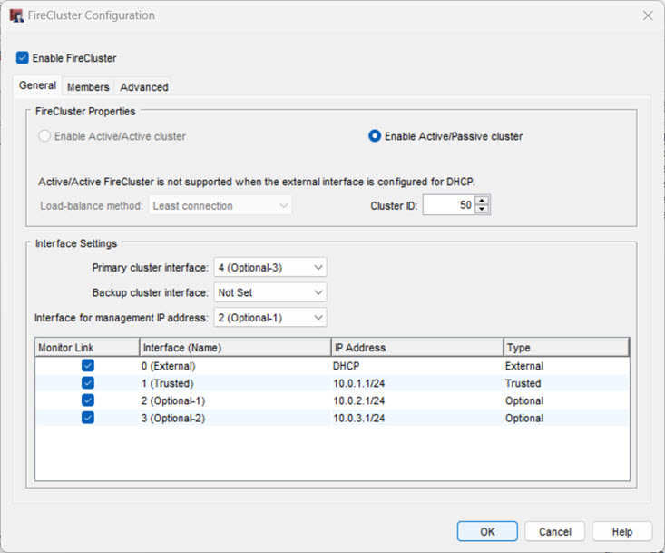
- Select the Enable FireCluster check box.
- Select which type of cluster you want to enable.
Enable Active/Passive Cluster
Enables the cluster for high availability, but not load sharing. If you select this option, the cluster has an active member that handles all the network traffic and a passive member that handles traffic only if a failover of the other member occurs.
Enable Active/Active Cluster
Enables the cluster for high availability and load sharing. If you select this option, the cluster balances traffic load across both cluster members.
- If you selected Enable Active/Active cluster, from the Load-balance method drop-down list, select the method to use to balance the traffic load between active cluster members.
Least Connection
If you select this option, each new connection is assigned to the active cluster member that has the lowest number of open connections.
Round-Robin
If you select this option, connections are distributed among the active cluster members in round-robin order. The first connection goes to one cluster member. The next connection goes to the other cluster member, and so on.
- From the Cluster ID drop-down list, select a number to identify this FireCluster.
In most cases you can use the default value. The cluster ID uniquely identifies this FireCluster if there is more than one FireCluster active on the same layer 2 broadcast domain. If you only have one cluster, and your network does not have VRRP devices, you can use the default value.
For an active/passive cluster, the Cluster ID determines the virtual MAC (VMAC) addresses used by the interfaces of the clustered devices. If you configure more than one active/passive FireCluster on the same subnet, it is important to know how to set the Cluster ID to avoid a possible virtual MAC address conflict.
For more information, go to Active/Passive Cluster ID and the Virtual MAC Address.
Configure Interface Settings
When you enable FireCluster, you must dedicate at least one interface to communication between the cluster members. This is called a cluster interface. When you set up the cluster hardware, you connect the primary cluster interfaces of each Firebox to each other.
For the best fault tolerance against network interface card (NIC) failure on the Firebox, we recommend that you use eth0 for the primary cluster interface. If a Firebox NIC fails, the Firebox automatically reassigns the logical interface numbers. The Firebox assigns "eth" labels in the order in which the interfaces are detected. As a result, logical interface numbers appear to shift to the left. Label reassignment can affect FireCluster operations and backup cluster interface configurations.
For example, if you use eth0 for the primary cluster interface, and a NIC other than eth0 fails, the FireCluster continues to operate as expected because the interface label remains eth0. The Firebox does not reassign the logical interface label for eth0 because there is no interface physically to the right of eth0. This configuration protects the FireCluster against NIC failures on interfaces other than eth0. Only an eth0 failure would affect FireCluster operations.
If you use eth4 as the primary cluster interface, and eth3 fails, the Firebox reassigns the logical label eth3. The interface eth4 becomes eth3. This disrupts FireCluster operations because the FireCluster configuration settings on the Firebox specify eth4 as the primary cluster interface.
Backup Cluster Interface
To add redundancy, you can configure a backup cluster interface. The primary and backup cluster interfaces must be on different subnets.
Before you specify a backup cluster interface, consider how a NIC failure can affect the backup cluster interface. For example, you specify eth3 as the primary cluster interface and eth4 as the backup cluster interface. If eth3 fails, the Firebox reassigns the logical label eth3. The interface that was labeled eth4 is now labeled eth3. The interface label reassignment disrupts FireCluster operations because the FireCluster configuration settings specify eth3 as the primary cluster interface and eth4 as the backup cluster interface.
We do not recommend a backup cluster interface in all cases:
FireCluster with a direct cable connection between cluster members
We recommend that you directly connect the backup cluster interfaces on each cluster member. However, we do not recommend a backup cluster interface for this type of configuration because it provides limited redundancy.
FireCluster operations use the backup cluster interface as expected only if the cable between the primary cluster interfaces fails. If any NIC on the Firebox fails, the backup cluster interface does not work as expected because the Firebox automatically reassigns the logical interface labels.
FireCluster with a switch between cluster members
In this configuration, FireCluster members are physically separated by a switch, which we do not recommend. If you must configure FireCluster in this way, we recommend that you configure a Backup Cluster Interface. The FireCluster uses the Backup Cluster Interface in these events:
- The cable between the switch and cluster interface fails
- The switch interface fails
- A networking issue causes the switch to become unavailable
If any NIC on the Firebox fails, the backup cluster interface does not work as expected because the Firebox automatically reassigns the logical interface labels. For the best results, use eth0 for the primary cluster interface.
If you use both primary and backup cluster interfaces, the interfaces must be on different subnets. We recommend that you do not use a switch between each member for the cluster interfaces. If you do use a switch between cluster members, the cluster interfaces must be logically separated from each other on different VLANs. We recommend that you configure a backup cluster interface if you separate the cluster interfaces with a switch.
You must disable any interfaces that are not connected to your network before you save the FireCluster configuration to the Firebox.
- From the Primary cluster interface drop-down list, select an interface to use as the primary interface.
- To use a second cluster interface, from the Backup cluster interface drop-down list, select an interface to use as the backup interface.
- Select an Interface for management IP address. This is the Firebox network interface you use to make a direct connection to a cluster device with any WatchGuard management application. You cannot select an external interface that uses PPPoE as the Interface for Management IP address. We recommend that you select the interface that the management computer usually connects to.
For more information, go to About FireCluster Management IP Addresses. - Review the list of monitored interfaces. The list of monitored interfaces does not include the interfaces you configured as the primary and backup cluster interfaces. By default, FireCluster monitors the link status for all enabled interfaces. If the cluster master detects a loss of link on a monitored interface, the cluster master starts failover.
- For an active/passive cluster, you can select which of the active interfaces to monitor. If you do not want to monitor the link status of an enabled interface as a criteria for failover, clear the check box for that interface in the Monitor Link column.
We recommend that you configure the FireCluster to monitor the link status of all enabled interfaces.
An active/active FireCluster always monitors the link status of all enabled network interfaces. For an active/active FireCluster, you must disable any interface that is not connected to a network switch.
To disable an interface:
- In Policy Manager, select Network > Configuration.
- Double-click the interface that you want to disable.
- Set the Interface Type to Disabled.
If you enable a physical interface or add a Link Aggregation interface after FireCluster is enabled, that interface is automatically selected as a monitored interface in the FireCluster configuration.
Configure FireCluster Members
- Select the Members tab.
The FireCluster members configuration settings appear.

If you previously imported a feature key in this configuration file, that device is automatically configured as Member 1.
If you do not have a feature key in this configuration file, a FireCluster member does not appear in the list. In this case, you must add each device as a member and import the configuration file for each device, as described in the next steps.
- To add a member, click Add.
The Add member dialog appears.
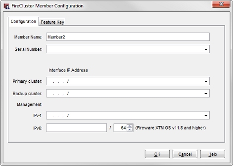
- In the Member Name text box, type a name. This name identifies this device in the members list.
- Select the Feature Key tab.
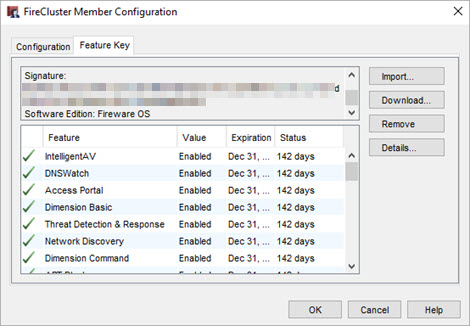
- Click Import.
The Import Firebox Feature Key dialog box appears. - To find the feature key file, click Browse.
Or, copy the text of the feature key file and click Paste to insert it in the dialog box. For more information, go to About Feature Keys and FireCluster. - Click OK.
- Select the Configuration tab.
The Serial Number field is automatically filled with the serial number from the feature key. - In the Interface IP Address section, type the addresses to use for each cluster interface and the interface for management IP address.
- In the Primary cluster text box, type the IP address to use for the primary cluster interface. The IP address for the primary cluster interface must be on the same subnet for each cluster member. The cluster member that has the highest IP address assigned to the primary cluster interface becomes the master if both devices start at the same time.
- In the Backup cluster text box, type the IP address to use for the backup cluster interface. This option only appears if you configured a backup cluster interface. The IP address for the backup cluster interface must be on the same subnet for each cluster member. The primary and backup cluster interfaces must be on different subnets.
If you use both primary and backup cluster interfaces, the interfaces must be on different subnets. We recommend that you do not use a switch between each member for the cluster interfaces. If you do use a switch between cluster members, the cluster interfaces must be logically separated from each other on different VLANs. We recommend that you configure a backup cluster interface if you separate the cluster interfaces with a switch.
- In the Management section, in the IPv4 text box, type the IP address to use to connect to an individual cluster member for maintenance operations. The interface for management is not a dedicated interface. It also is used for other network traffic. You must specify a different management IP address for each cluster member. The IPv4 management IP address must be an unused IP address. We recommend that you use an IP address on the same subnet as the IPv4 address assigned to the interface. It must also be on the same subnet as the WatchGuard Log Server or syslog server that your FireCluster sends log messages to.
- If the interface that you selected as the Interface for management IP address has IPv6 enabled, you can also configure an IPv6 management IP address. In the Management section, in the IPv6 text box, type the IPv6 address to use to connect to an individual cluster member for maintenance operations. The IPv6 management IP address must be an unused IP address. We recommend that you use an IP address that has the same prefix as an IPv6 IP address assigned to the interface.
For more information, go to About FireCluster Management IP Addresses. - Click OK.
The device you added appears on the Members tab as a cluster member. - Repeat the previous steps to add the second device to the cluster configuration.
To automatically discover the second Firebox and add it to the cluster, do not save the configuration file until you start the second device in a factory-default state.
- Before you save the configuration of the cluster master Firebox to enable FireCluster:
- Start the second Firebox with factory-default settings. Use the reset instructions for your Firebox model. For more information, go to Reset a Firebox.
- Connect the cluster interface of the cluster master Firebox to the cluster interface of the second Firebox member of the FireCluster.
- Save the configuration to the cluster master Firebox.
When you save the configuration with FireCluster enabled to the Firebox:
- The Firebox restarts and becomes the cluster master.
- The cluster master Firebox uses the cluster interface to automatically discover the second cluster member Firebox.
- When the cluster master Firebox discovers a connected device with factory-default settings, it verifies that the serial number matches the serial number in the FireCluster configuration, and then sends the cluster configuration to the second device.
- The second device then joins the cluster and synchronizes all cluster status with the cluster master.
View FireCluster Status and Troubleshoot
After the cluster is active, you can monitor the status of the cluster members on the Firebox System Manager Front Panel tab or from Fireware Web UI. For more information, go to Monitor and Control FireCluster Members.
If the second device is not automatically discovered, you can manually trigger device discovery as described in Discover a Cluster Member.
For more information on how to troubleshoot cluster formation issues, go to Troubleshoot FireCluster.
FireCluster Formation Alternate Method
To more easily troubleshoot cluster members that do not join the cluster with the auto-discovery method because of network issues or a Fireware version mismatch, you use the alternate cluster formation method to save the Firebox configuration to both devices.
The alternate method enables you to view error and log messages about reasons why the cluster was not formed. For more information, go to Alternate FireCluster Configuration.
Connect the FireCluster to the Network
Now that the cluster is successfully formed, you can connect the Fireboxes to your network, as described in Connect the FireCluster Hardware
