Applies To: Locally-managed Fireboxes
Before you connect the FireCluster hardware, review the list of FireCluster requirements and the switch and router requirements.
To connect two Fireboxes in a FireCluster configuration that have modular network interfaces, go to About FireCluster with Modular Interfaces.
This diagram shows connections for a simple FireCluster configuration.

In this example:
- The FireCluster has one external and one trusted interface connected to network switches.
- The primary cluster interfaces are connected by an Ethernet cable. Make sure your Ethernet cables are a minimum 1m (3ft) or longer.
To connect two Fireboxes in a FireCluster configuration:
- Use an Ethernet cable (straight or crossover cable) to connect the primary cluster interface on one Firebox to the primary cluster interface on the other Firebox.
- If you plan to enable a backup cluster interface, use a second Ethernet cable to connect the backup cluster interfaces. If you have a network interface available, we recommend that you connect and configure a backup cluster interface for redundancy.
If you use both primary and backup cluster interfaces, the interfaces must be on different subnets. We recommend that you do not use a switch between each member for the cluster interfaces. If you do use a switch between cluster members, the cluster interfaces must be logically separated from each other on different VLANs. We recommend that you configure a backup cluster interface if you separate the cluster interfaces with a switch.
- Connect the external interface of each Firebox to a network switch or VLAN. If you use Multi-WAN, connect the second external interface of each Firebox to another network switch.
- Connect the trusted interface of each device to an internal network switch or VLAN.
- For each Firebox, connect the other trusted or optional network interfaces to the internal network switch for that Firebox.
When you configure the FireCluster, do not connect your second Firebox to the cluster until you have configured the first Firebox that will be the cluster master.
Caution: If any interface on the Firebox configuration uses the IP address 10.0.1.1, do not connect the trusted and optional network interfaces of the second device to the switches until after the cluster has been formed. This avoids an IP address conflict when you start the second device with factory-default settings. The devices use the cluster interfaces to form the cluster. After the you save the configuration to the cluster master, and the cluster is active, connect each of the trusted and optional interfaces of the second device to the appropriate switches.
When you are ready to configure the FireCluster in WatchGuard System Manager, go to Configure FireCluster.
Multi-WAN Configuration
This diagram shows connections for a multi-WAN FireCluster configuration where you have connections to multiple ISPs through a layer 2 external network switch for each ISP.
In this example, each Firebox in the FireCluster has two external interfaces that connect to the external network switch for each ISP, and one trusted interface connected to the internal network switch. The primary cluster interfaces are connected by an Ethernet cable.
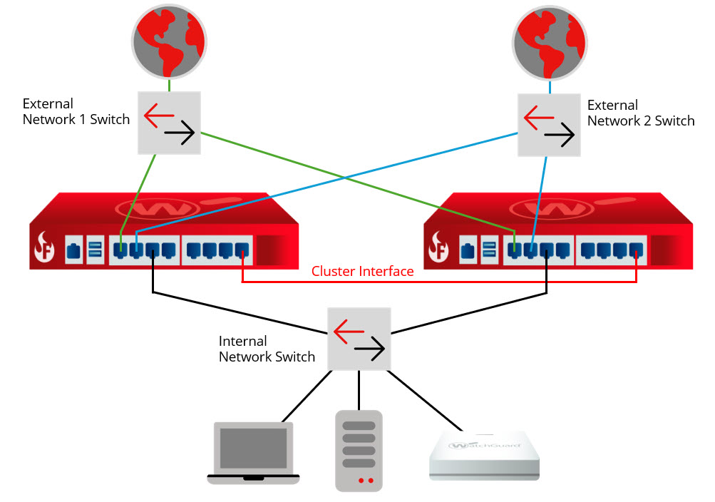
For a multi-WAN FireCluster configuration, we recommend you use two external layer 2 switches for connections to each ISP. Do not use a single managed switch with VLAN trunks for each ISP because the switch will be a single point of failure.
Configure FireCluster with the Setup Wizard
Configure FireCluster Manually