Configure Tunnel Interfaces
Applies To: Wi-Fi Cloud-managed Access Points (AP125, AP225W, AP325, AP327X, AP420)
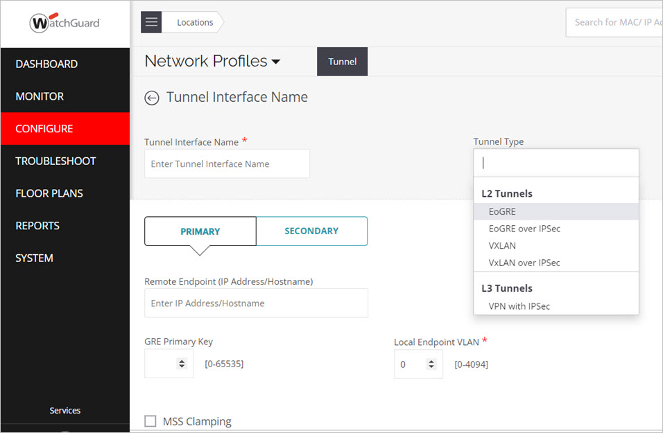
Wi-Fi Cloud supports these types of tunneling protocols:
- EoGRE (Ethernet over GRE)
- EoGRE over IPSec
- VXLAN (Virtual Extensible LAN)
- VXLAN over IPSec
- IPSec VPN
EoGRE
Generic Routing Encapsulation (GRE) is a tunneling protocol that can encapsulate a variety of network layer protocols inside virtual point-to-point links over an IP network. EoGRE provides the ability to set up one or more tunnels from the AP to an aggregating device. Traffic from one or multiple SSIDs can be channeled through these tunnels.
EoGRE over IPSec
You can also use IPSec with EoGRE to add encryption for encapsulated data to provide a secure and flexible VPN solution. With IPSec, an extra layer of security is added to the GRE packets to protect sensitive information against eavesdropping or any modification. EoGRE over IPSec is supported in either Tunnel or Transport mode. Security of GRE packets is measured by these phases:
- Phase I — This phase describes different security mechanisms used to authenticate and validate the keys shared between the endpoints.
- Phase II — This phase describes different methods to encrypt the payload of the packet, to provide a high level of privacy, confidentiality, and security from spoofing or any possible threat of tampering.
When you configure tunnel profiles, you can specify a primary endpoint and a secondary endpoint. The wireless traffic is bridged to the secondary endpoint when the primary endpoint fails. The secondary endpoint is optional and is functional only if you enable a secondary endpoint and configure the host name and local endpoint VLAN for the secondary endpoint. The secondary endpoint checks for the availability of the primary endpoint and transfers control to the primary endpoint when it is up and running.
VXLAN
VXLAN was developed to overcome the limited scalability of VLANs in large network deployments. VXLAN creates a virtual network on top of a physical network. The virtual network is called an overlay and the physical network infrastructure it runs on is called an underlay. Switches and routers that participate in VXLAN have a special interface called a VTEP.
The VTEP provides the connection between the underlay and the overlay. The Ethernet frames that travel over the VXLAN tunnel are encapsulated in IP and UDP headers at the source host and decapsulated at the destination client. APs support VXLAN to allow tunneling of data from Wi-Fi APs to a central aggregation point, such as a VXLAN-capable switch. This allows you to migrate your existing controller-based Wi-Fi networks to Wi-Fi Cloud without having to change the design of their underlying campus network.
VXLAN over IPSec
With VXLAN over IPSec, VXLAN creates the virtual network, and IPSec adds a layer of security to the wireless traffic with encryption. This adds an extra layer of security to the VXLAN packets to protect client’s data from interception or modification.
IPSec VPN
IPSec is a collection of cryptography-based services and security protocols that protect communication between devices that send traffic through an untrusted network.
You can configure an IPSec VPN tunnel for use with the Remote AP VPN feature. When a Wi-Fi client connects to a remote AP through the SSID set up for the corporate network, the AP establishes an IPSec VPN tunnel to the corporate network. The tunnel securely carries network traffic between Wi-Fi clients and the corporate network. For more information, see Remote Access Point.
Configure a Tunnel Interface
To create a tunnel interface profile in Discover:
- Open Discover.
- Select Configure > Network Profiles > Tunnel.
- Click Add Tunnel Interface.
- Select the Tunnel Type.
- Define the values for the selected tunnel interface type:
EoGRE Tunnel Interface
- Type the Profile Name of the tunnel interface.
- Type the IP address or hostname of the primary Remote Endpoint.
- Select the GRE Primary Key for the primary endpoint GRE header. The key should be the same at both ends of the tunnel. It is not mandatory for the key to be configured in the GRE tunnel.
- Select the Local Endpoint VLAN ID through which the AP will form a tunnel to the remote endpoint. The value must be between 0 and 4094. The Remote Endpoint must be reachable through this VLAN.
- Repeat these steps for the Secondary Endpoint. The secondary endpoint is the remote endpoint to which wireless traffic is diverted if the primary endpoint is not available.
- (Optional) Select Prefer Primary Endpoint if you want the AP to check for the availability of the primary tunnel. If the check box is not selected and the primary tunnel is down, the AP continues to operate on the secondary tunnel.
EoGRE over IPSec
- Type the Profile Name of the tunnel interface.
- Type the IP address or hostname of the primary Remote Endpoint.
- Select the GRE Primary Key for the primary endpoint GRE header. The key should be the same at both ends of the tunnel. It is not mandatory for the key to be configured in the GRE tunnel.
- Select the Local Endpoint VLAN ID through which the AP will form a tunnel to the remote endpoint. The value must be between 0 and 4094. The Remote Endpoint must be reachable through this VLAN.
- Repeat these steps for the Secondary Endpoint. The secondary endpoint is the remote endpoint to which wireless traffic is diverted if the primary endpoint is not available.
- (Optional) Select Prefer Primary Endpoint if you want the AP to check for the availability of the primary tunnel. If the check box is not selected and the primary tunnel is down, the AP continues to operate on the secondary tunnel.
- Click Configure IPSec.
- Type the IP address of the Remote Endpoint.
- Select the Mode (Transport of Tunnel):
- Tunnel Mode: Encrypt the entire IP header of the original packet. IPSec wraps the EoGRE packet, encrypts it, adds a new set of IP headers (ESP header), and sends it across the VPN tunnel.
- Transport Mode (default): In Transport mode, only the payload and Encapsulating Security Payload (ESP) trailer is encrypted. The IP header of the original packet is not encrypted.
- Configure your Phase 1 and Phase 2 parameters. For more information. see Phase 1 and Phase 2 IPSec Parameters.
VXLAN
- Type the Profile Name of the tunnel interface.
- Type the IP address or hostname of the primary Remote Endpoint.
- Select the Local Endpoint VLAN ID through which the AP will form a tunnel to the remote endpoint. The value must be between 0 and 4094. The Remote Endpoint must be reachable through this VLAN.
- Repeat these steps for the Secondary Endpoint. The secondary endpoint is the remote endpoint to which wireless traffic is diverted if the primary endpoint is not available.
- (Optional) Select Prefer Primary Endpoint if you want the AP to check for the availability of the primary tunnel. If the check box is not selected and the primary tunnel is down, the AP continues to operate on the secondary tunnel.
- Click Configure IPSec.
- Type the IP address of the Remote Endpoint.
- Select the Mode (Transport of Tunnel):
- Tunnel Mode: Encrypt the entire IP header of the original packet. IPSec wraps the EoGRE packet, encrypts it, adds a new set of IP headers (ESP header), and sends it across the VPN tunnel.
- Transport Mode (default): In Transport mode, only the payload and Encapsulating Security Payload (ESP) trailer is encrypted. The IP header of the original packet is not encrypted.
- Configure your Phase 1 and Phase 2 parameters. For more information. see Phase 1 and Phase 2 IPSec Parameters.
VXLAN over IPSec
- Type the Profile Name of the tunnel interface.
- Type the IP address or hostname of the primary Remote Endpoint.
- Select the Local Endpoint VLAN ID through which the AP will form a tunnel to the remote endpoint. The value must be between 0 and 4094. The Remote Endpoint must be reachable through this VLAN.
- Repeat these steps for the Secondary Endpoint. The secondary endpoint is the remote endpoint to which wireless traffic is diverted if the primary endpoint is not available.
- (Optional) Select Prefer Primary Endpoint if you want the AP to check for the availability of the primary tunnel. If the check box is not selected and the primary tunnel is down, the AP continues to operate on the secondary tunnel.
VPN with IPSec
- Type the Tunnel Interface Name for the tunnel interface.
- Type the IP address or hostname of the primary Remote Endpoint.
- Select the Local Endpoint VLAN ID through which the AP will form a tunnel to the remote endpoint. The value must be between 0 and 4094. The Remote Endpoint must be reachable through this VLAN.
- Configure the Phase 1 and Phase 2 parameters for the IPSec tunnel. For more information, see Phase 1 and Phase 2 IPSec Parameters.
- Repeat these steps for the Secondary Endpoint. The secondary endpoint is the remote endpoint to which wireless traffic is diverted if the primary endpoint is not available.
- (Optional) You can clamp the maximum segment size (MSS) to a value lower than the tunnel maximum transmission unit (MTU) value. This makes sure that no packet that passes through the tunnel exceeds the tunnel MTU size. For more information, see About MSS Clamping.
- Select the MSS Clamping check box.
- Select Manual or Auto Tunnel MTU Discovery.
- If you select Manual, type the tunnel MTU size. The default is 1550 bytes. You can type a value from 1000 to 1700 bytes.
- Click Save.
Phase 1 and Phase 2 IPSec Parameters
|
Field |
Description |
|---|---|
|
Phase 1 parameter |
|
| IKE Settings |
|
| IKE Versions |
IKE (Internet Key Exchange) version 1 or version 2 (default). |
| AP Authentication Method |
A list of methods used to authenticate an AP. The available options are:
|
| Identifier | Type a unique name to identify an AP endpoint. If blank, the local VLAN endpoint IP address is used as the identifier. |
| PSK key input | Type a pre-shared key. Available only if PSK is selected. |
| Username |
Name of the user. This option is not available if PSK is selected. |
| Password |
Type a password. This option is not available if PSK is selected. |
|
EAP method |
Methods used to authenticate an AP. The available options are:
This option is available only if EAP is selected. |
| AAA Identity | AAA (authentication, authorization, and accounting) controls access to APs, and enforces policies and device usage for effective network security. Type the identity of the RADIUS server. This option is available only if EAP is selected. |
| Remote Authentication Method |
A list of methods used to authenticate an endpoint. The available options are:
|
| Identifier | Type a unique name to identify a remote endpoint. |
| PSK key input |
Type a pre-shared key. This option is not available if IKE Version 1 is selected with PSK as the AP Authentication Method. |
|
Public Key Authentication |
Select this option to exchange a public key between endpoints to authenticate the identity of each endpoint. The public keys are exchanged in messages that contain a digital certificate. Click Set certificate to apply a digital signature on the generated keys. |
| Phase 1 Combination of Cipher | |
| Cipher Algorithm |
Specify the algorithm to use to encrypt the data packets traversing through the VPN tunnel. These algorithms are supported:
|
|
Cipher Length |
Type the length of key in bits. Longer keys provide greater security. |
|
Hash Algorithm |
Specify the algorithm to use to authenticate the message sent through the VPN tunnel. These algorithms are supported:
|
|
DH Group |
Select the Diffie-Hellman group algorithm from the available options. |
| Phase 2 Parameter Payload Encryption | |
| Life time/Phase two keep alive | IKE keep alive is the time (in hours) for which the generated keys are active. After the specified time period, new keys are generated and shared between the endpoints. |
| Phase 1 Combination of Cipher | |
| ESP |
ESP (Encapsulating Security Payload) encrypts the entire packet and provides the ability to authenticate senders and keep data private. |
| AH | AH (Authentication Header) only provides message authentication. AH only lets the receiver verify that the message is intact and unaltered, but it does not encrypt the message on its own. Packets are authenticated using a checksum created by using a hash-based message authentication code (HMAC) in connection with a key. |
| Cipher Algorithm |
Specify the algorithm used to encrypt the data packets traversing through the VPN tunnel. These algorithms are supported:
|
| Cipher Length | Type the length of key in bits. Longer keys provide greater security. |
|
Hash Algorithm |
Specify the algorithm to use to authenticate the message sent through the VPN tunnel. These algorithms are supported:
|
|
DH Group |
Select the Diffie-Hellman group algorithm from the available options. |
About MSS Clamping
The maximum transmission unit (MTU) determines the maximum allowable size of a packet in the network path.
When you tunnel Wi-Fi traffic to a wired endpoint, the frame size of each packet increases by 50 to 200 bytes because of headers added by each protocol layer. Because this new frame size might be larger than the tunnel MTU, packets are either fragmented or combined into jumbo frames. These techniques can cause issues in tunneled networks because tunnel endpoints might not support fragmentation and reassembly
You can enable support for maximum segment size (MSS) clamping for tunneled networks. When you enable MSS, APs clamp the maximum segment size to a value lower than the tunnel maximum transmission unit (MTU) value. This makes sure that no packet that passes through the tunnel exceeds the tunnel MTU size.
When a Wi-Fi client attempts to set up a TCP connection with an MSS larger than the tunnel MTU, the AP modifies the MSS value in the TCP messages so that the packet size does not exceed the tunnel MTU.
Manual and Automatic Tunnel MTU Discovery
You can use automatic or manual tunnel discovery. We recommend that you manually set the tunnel MTU value.
When you use automatic tunnel MTU discovery, an AP must determine the tunnel MTU based on the ICMP "Fragmentation Needed" messages sent from switches and routers along the tunnel. Switches and routers send this message when they discard a packet larger than their MTU size. The ICMP “Fragmentation Needed” message contains the MTU value set by the switch or router. The AP lowers the MTU value until it no longer receives these ICMP messages.
In many deployments, ICMP is disabled on switches and routers for security reasons, and packets larger than their MTU size are discarded without ICMP notification messages. In this case, an AP cannot determine the tunnel MTU and uses the default value of 1500 bytes that might not be the correct tunnel MTU value.