Deployment Overview
Proxmox Virtual Environment (VE) is an open-source server virtualization platform that enables you to deploy and manage virtual machines and containers on commodity hardware. You can use Proxmox VE to host a FireboxV virtual machine and provide enterprise-grade network security in a virtualized environment.
This document explains how to deploy a FireboxV virtual machine on a Proxmox VE hypervisor and complete the initial configuration with the Fireware Web Setup Wizard.
FireboxV deployment on Proxmox VE is supported in Fireware v12.11.2 and higher. Proxmox also supports FireCluster. Both FireboxV instances must run on the same Proxmox cluster. For more information about FireCluster requirements, go to About FireCluster in Help Center.
Platform and Software
The hardware and software required to complete the procedures in this document include:
- Proxmox VE 8.x and higher.
- FireboxV with Fireware v12.11.2 and higher.
Recommended resources for FireboxV vary by model. This table lists the minimum recommended resources for each FireboxV model:
| FireboxV Model | Memory | Maximum vCPUs | Disk Space |
|---|---|---|---|
| Micro | 2048 MB* | 2 | 5 GB |
| Small | 2048 MB* | 2 | 5 GB |
| Medium | 4096 MB | 4 | 5 GB |
| Large | 4096 MB | 8 | 5 GB |
| Extra Large | 4096 MB | 16 | 5 GB |
* 4096 MB memory is required to enable IntelligentAV.
For the full list of FireboxV system requirements, go to the FireboxV System Requirements section of the Operating System Compatibility Matrix in the Fireware Release Notes.
Test Topology
This diagram shows the test topology for this deployment.
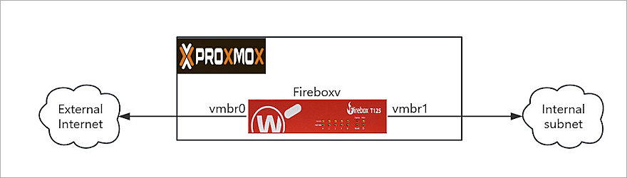
In this topology, Proxmox VE runs on a physical server with two network bridges:
- vmbr0 — Connected to the external (WAN) network.
- vmbr1 — Connected to the internal (LAN) network.
The FireboxV virtual machine connects to both bridges and acts as the gateway and firewall between the internal network and the external network.
Before You Begin
Before you deploy FireboxV on Proxmox VE, make sure you have:
- FireboxV device serial number.
You receive the serial number when you purchase the FireboxV virtual device. - WatchGuard FireboxV .ova file.
The file name isFireboxV_<version>.ova, where<version>is the Fireware version number. Download the file from the WatchGuard Software Downloads page. - Proxmox VE 8.0 or higher.
Make sure your Proxmox server has at least two configured network bridges — one for the external (WAN) network and one for the internal (LAN) network. - SSH access or Proxmox Web Console shell access to the Proxmox server.
You must have shell access to run the commands required to extract and deploy the FireboxV virtual machine.
Upload and Extract the FireboxV Image
WatchGuard provides the FireboxV image as an .OVA (Open Virtual Appliance) file. The .OVA file includes an .OVF configuration file and a .VMDK disk image file. To deploy FireboxV on Proxmox, upload the .OVA file to the Proxmox server and extract its contents.
- Upload the FireboxV .OVA file to the /tmp directory on the Proxmox server. You can use SCP, SFTP, or the Proxmox Web Console to upload the file. For example, from a local computer type:
scp FireboxV_12_11_2.ova root@<proxmox-ip>:/tmp/ - Log in to the Proxmox server shell through SSH or the Proxmox Web Console.
- Create a working directory and extract the contents of the .OVA file:
mkdir /tmp/fireboxv
tar xvf /tmp/FireboxV_12_11_2.ova -C /tmp/fireboxv/ - Verify the extracted files:
ls -lh /tmp/fireboxv/
You now have an .OVF file and one or more .VMDK disk image files.
Deploy the FireboxV Virtual Machine
After you extract the .OVA file, use the Proxmox qm command‑line tool to import the .OVF configuration and create the FireboxV virtual machine.
Import the OVF and Create the Virtual Machine
Use the Proxmox qm importovf command to import the .OVF configuration and create the FireboxV virtual machine:
- In the Proxmox shell, navigate to the directory that contains the extracted files:
cd /tmp/fireboxv - Run the qm importovf command to create the virtual machine and import the disk image:
qm importovf 200 /tmp/fireboxv/FireboxV_12_11_2_signed.ovf local-lvm
In this command, 200 is the virtual machine ID, FireboxV_12_11_2_signed.ovf is the extracted OVF file, and local-lvm is the Proxmox storage name. Replace these values as required for your environment.
Configure the Virtual Machine Settings
The qm importovf command creates the virtual machine but does not configure all required settings.
To configure the virtual machine name, memory, CPU, and storage settings:
- To set the virtual machine name, memory, CPU, and operating system, type:
qm set 200 --name fireboxv --memory 4096 --cores 4 --sockets 1 --cpu host --ostype l26
Adjust the --memory and --cores values based on your FireboxV model. For more information, go to the resource table in the Platform and Software section of this guide. - Set the SCSI controller to VirtIO:
qm set 200 --scsihw virtio-scsi-pci - Verify the current virtual machine configuration and confirm the imported disk name:
qm config 200 - In the output, locate an unused disk entry. For example, unused0: local-lvm:vm-200-disk-0. Make a note of the disk name for use in the next step.
- Attach the imported disk to the virtual machine as SCSI device 0:
qm set 200 --scsi0 local-lvm:vm-200-disk-0
Replace vm-200-disk-0 with the disk name from the previous step, if it differs. - Set the boot order to startup from the SCSI disk:
qm set 200 --boot order=scsi0
Create Internal Network Bridge (Laptop Use)
When you install Proxmox on a laptop with only one physical network port, create a virtual bridge (vmbr1) for the internal network:
- Log in to the Proxmox Web UI at:
https://<your-laptop-ip>:8006 - From the left navigation pane, click your node. For example, proxmox-test.
- Click Network in the left navigation pane.
- In the upper‑right, click Create > Linux Bridge.
- Configure the bridge with these settings:
- Name:
vmbr1 - IPv4/CIDR: Leave blank
- Autostart: Select
- Comment: Internal Network for FireboxV (optional)
- Name:
- Click Create.
After you create the bridge, vmbr1 appears in the network list.
Configure Network Interfaces
FireboxV requires at least two network interfaces: one for the external (WAN) network and one for the trusted (LAN) network.
- Add the external network interface:
qm set 200 --net0 virtio,bridge=vmbr0
Replace vmbr0 with the bridge that connects to your external (WAN) network. - Add the trusted network interface:
qm set 200 --net1 virtio,bridge=vmbr1
Replace vmbr1 with the bridge that connects to your internal (LAN) network.
Start the FireboxV Virtual Machine
Start the FireboxV virtual machine and monitor the initial startup process in the Proxmox interface.
- Start the virtual machine:
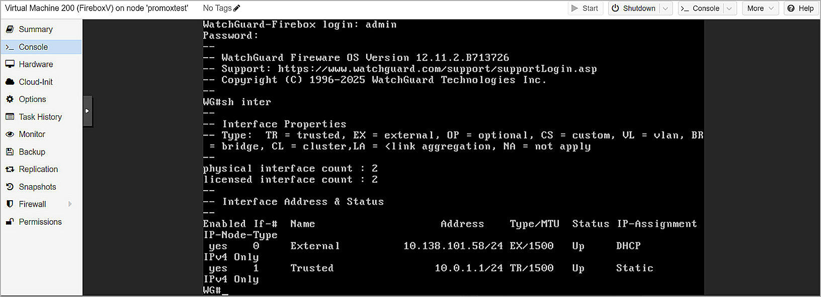
qm start 200 - In the Proxmox web interface, select the virtual machine, then click Console to monitor the startup process.
- Wait for FireboxV to complete startup.
The initial startup requires additional time while FireboxV initializes. When startup completes, the Fireware Web UI becomes available.
Complete the Initial Configuration
Use the Fireware Web Setup Wizard to create a basic configuration for the FireboxV. For FireboxV, you can connect to either the external interface or the trusted interface to run the wizard. After the wizard completes, the virtual machine reboots to apply the new serial number.
WARNING: If you do not complete all steps of the Web Setup Wizard within 15 minutes, the wizard discards your settings. You must then log in and restart the wizard.
- On a computer connected to the FireboxV network, open a web browser and connect to the Fireware Web UI:
- External interface — Connect from any computer on the external network:
https://<External_IP_Address>:8080
Use the IP address that your DHCP server assigns to the external interface. You can find this address in the DHCP server lease table. - Trusted interface — Connect from any computer on the trusted (internal) network:
https://10.0.1.1:8080
- External interface — Connect from any computer on the external network:
- Log in with the default administrator credentials:
- Username —
admin - Passphrase —
readwrite
- Username —
- Complete all steps in the Web Setup Wizard.
The wizard includes a step to activate your FireboxV device with a feature key. You must activate the device to enable licensed features and assign a serial number. - After the wizard completes, the FireboxV reboots with the new serial number.
If you change the IP address of the interface you used to connect to the wizard, reconnect to the new IP address to manage the device.
After you complete setup, the basic configuration allows outbound TCP, UDP, and ping traffic and blocks all unrequested traffic from the external network. Default policies and services use recommended settings.