About Spanning Tree Protocol
Applies To: Locally-managed Fireboxes
You can enable Spanning Tree Protocol for:
LAN bridges
For information about how to enable Spanning Tree Protocol for a network bridge, go to Create a Network Bridge Configuration.
Bridge mode
For information about how to enable Spanning Tree Protocol for a Firebox configured in Bridge mode, go to Bridge Mode.
VLANs
For information about how to enable Spanning Tree Protocol for a VLAN, go to Define a New VLAN.
Spanning Tree Protocol support for VLANs includes:
- Single tagged VLAN between Fireboxes
- Single untagged VLAN between Fireboxes
- Single untagged VLAN between a Firebox and a third-party switch
- Multiple tagged or untagged VLANs between Fireboxes
Configurations that are not supported:
- Multiple tagged or untagged VLANs between a Firebox and a third-party switch
- A single tagged VLAN between a Firebox and a third-party switch
Spanning Tree Protocol is not supported for FireCluster.
To work with the Firebox, switches with Rapid Spanning Tree Protocol (RSTP) must be backward compatible with STP. Multiple Spanning Tree Protocol (MSTP) and proprietary STP protocols are not supported.
This topic includes basic information about Spanning Tree Protocol. For detailed technical information about Spanning Tree Protocol, see IEEE 802.1D. For information about how to configure a switch for Spanning Tree Protocol, see the documentation for your switch.
You can only change the default Spanning Tree Protocol settings from the Fireware Command Line Interface (CLI). For more information about the default Spanning Tree Protocol settings, go to Configure Spanning Tree Protocol Settings in the CLI.
Topology
Spanning Tree Protocol runs on switches and bridges on a LAN. Because Spanning Tree Protocol operates on Layer 2 of your network, you can enable this feature without any impact to Firebox performance.
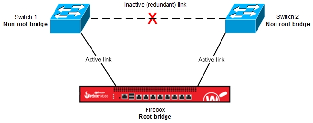
In a Spanning Tree implementation, your network topology has a tree structure. A root bridge switch is located at the bottom of the tree. The other switches in your network, non-root bridges, are located along the tree branches.
The root bridge manages your redundant links to make sure that there is only one active path to each location on your network. If more than one path to a location exists, the Spanning Tree Algorithm calculates the best path, and blocks redundant links so they cannot forward packets. This prevents loops on the network.
If an active link becomes unavailable, network communication automatically fails over to a redundant link. For more information about link failover, go to the Topology Changes and Link Failover section.
This diagram shows a simple implementation of Spanning Tree with the Firebox as the root bridge:
Communication Between Bridges
To communicate with each other, root and non-root bridges send Bridge Protocol Data Units (BPDUs) on the network. A BPDU is a small packet that specifies the Bridge ID, Path cost, Port ID, and other information.
Bridge ID
A Bridge ID (BID) is an identifier used to select the root bridge. It contains the bridge priority and the MAC address of the bridge. The smaller the bridge priority number, the higher the priority.
Bridge priority values:
- Minimum bridge priority — 0
- Default bridge priority — 32,768
- Range — 0–32,768
Path cost
Path cost is a value associated with the link speed (bandwidth) of the links between bridges. If the link speed or duplex settings of a port changes, Spanning Tree Protocol automatically recalculates the path cost.
This list shows the path costs specified by IEEE 802.1D.
| Link Speed Between Bridges | Default Path Cost |
|---|---|
| 10 Gbps | 2 |
| 1 Gbps | 4 |
| 100 Mbps | 19 |
| 10 Mbps | 100 |
Port ID
The port ID contains the bridge priority and the interface identifier. The smaller the port ID, the higher the priority.
Switches configured for Spanning Tree Protocol send three kinds of BPDUs on your network:
- Topology Change Notification (TCN) — Sent by a non-root bridge to the root bridge to announce a topology change.
- Topology Change Acknowledgment (TCA ) — Sent by the root bridge to the non-root bridge that reported a topology change. After the non-root switch receives the TCA, it no longer broadcasts the TCN.
- Configuration — Sent by a root bridge to the entire network at an interval specified by the hello value. For the Firebox, the default interval is 2 seconds. You can change the hello value from the Fireware CLI.
Root Bridge and Port Selections
When you enable Spanning Tree Protocol, the topology convergence selection process automatically occurs. The bridges in your network send BPDUs to each other to:
Step 1 — Select One Root Bridge
One bridge on your network is selected as the root bridge.
To select a root bridge, the Bridge ID (which contains the bridge priority and MAC address) is examined. The bridge with the lowest bridge priority value is selected as the root bridge. If all bridge have the same bridge priority, the bridge with the lower MAC address value becomes the root bridge. The root bridge sends BPDUs to the non-root bridges to identify itself as the root bridge.
You can configure the Bridge ID settings so a specific switch on your network is always the root bridge. For example, you might want the root bridge to be a centralized switch that is not directly connected to user computers on your network.
From the Fireware CLI, you can specify the Firebox as the root bridge:
- Change the bridgeprio value to a number than is lower than all other bridges.
- To specify a particular switch as a backup root bridge, specify the next highest bridgeprio value to that switch.
Step 2 — Select the Root Ports
The root port is the port on a non-root bridge that is closest to the root bridge.
Every non-root bridge selects one root port based on the path cost. The port with the lowest path cost to the root bridge becomes the root port. For example, a 10 Mbps link has a path cost of 100. A 10 Gbps link has a path cost of 2. The port associated with the 10 Gbps link becomes the root port because it has the lowest path cost.
If all ports have the same path cost, the port with the lowest Bridge ID becomes the root port. If all ports have the same path cost and Bridge ID, the port with the lowest port priority becomes the root port.
For more information about path cost and port selections, see IEEE 802.1D or the documentation for your switch.
Step 3 — Select the Designated Ports
Designated ports exist on root and non-root bridges:
- All ports on a root bridge are designated ports.
- On a non-root bridge, the designated port is the uplink to the next non-root bridge in the tree.
Non-designated ports are ports that are not allowed to forward packets. A redundant link between a non-designated port and a designated port is inactive, which prevents a network loop.
This diagram shows the root ports, designated ports, and non-designated ports in a simple Spanning Tree implementation.

Topology Changes and Link Failover
To understand what occurs after a topology change, you must understand port states. In the Spanning Tree model, an enabled switch port can be in one of four states:
- Blocking — Receives BPDUs only
- Listening — Processes BPDUs and builds an active topology
- Learning — Builds the MAC table
- Forwarding — Sends and receives data
If a bridge detects that one of its ports is unavailable, and a redundant port exists, the bridge automatically changes the state of the redundant port from blocking to forwarding.
For example, if a root port fails on a non-root bridge, the redundant port on that bridge changes state from blocking to forwarding. After the state of the redundant port changes to forwarding, the port becomes the new root port.
The bridge sends a BPDU to the root bridge to announce the topology change. The root bridge sends a BPDU to the non-root bridge to acknowledge the change. Next, the root bridge sends a BPDU to all the bridges on your network to announce the change. If there is a loop on the network, topology convergence occurs, as described in the previous section.
Failover from an active link to a redundant link is automatic, but not instantaneous. There is a delay between the time a forwarding port becomes unavailable, and when the port state changes from blocking to forwarding. It also takes times for the bridges on your network to update their MAC address tables.
Default Settings
When you enable Spanning Tree Protocol in the Firebox configuration, default values are used for the bridge priority and other settings. For more information about how to change the default Spanning Tree Protocol settings, go to Configure Spanning Tree Protocol Settings in the CLI.