Configure BOVPN over WireGuard
Applies To: Locally-managed Fireboxes
Some of the features described in this version of Fireware Help are only available to participants in the WatchGuard Beta program. If a feature described in this topic is not available in your version of Fireware, it is a beta-only feature.
In Fireware v2026.4 or higher, you can configure a WireGuard branch office virtual private network (BOVPN) tunnel between Fireboxes. WireGuard uses a peer-based configuration model. Each Firebox endpoint includes a local WireGuard interface and one or more peer definitions. When you create the WireGuard interface, the Firebox generates a public and private key pair. The Firebox stores the private key securely and shows the public key in the UI. To establish a WireGuard tunnel, configure each Firebox with the public key of the remote peer.
For more information about BOVPN over WireGuard, go to About BOVPN over WireGuard.
BOVPN over WireGuard Configuration Workflow
To create a WireGuard BOVPN tunnel between two Fireboxes, complete the configuration in this order:
- On each Firebox, enable WireGuard and configure a unique Interface Address for the local WireGuard interface.
- On each Firebox, add a peer tunnel to the remote Firebox. When you configure the peer tunnel, paste the public key from that remote Firebox, and specify the endpoint address and UDP listening port for that remote Firebox.
- On each Firebox, add allowed resources for the private networks behind the remote Firebox.
- Save the configuration on both Fireboxes.
- Send traffic between the private networks to initiate the tunnel, then verify peer status and routes.
On each Firebox, allowed resources are the networks behind the remote Firebox. Do not add only the local networks as allowed resources.
This example shows settings for a site-to-site WireGuard BOVPN between two Fireboxes. Use these values as a guide when you configure each peer. The WireGuard Interface Address on each Firebox must be a unique host IP address that does not conflict with any other interface network on that Firebox. The peer Interface Address must be in a different network from the local WireGuard Interface Address.
| Setting | Site A Firebox | Site B Firebox |
|---|---|---|
| External interface IP address | 203.0.113.2 | 198.51.100.2 |
| Trusted network | 192.0.1.0/24 | 192.1.1.0/24 |
| WireGuard Interface Address | 10.10.10.1 | 10.10.20.1 |
| Listening Port | 442 | 442 |
| Peer Endpoint Address | 198.51.100.2 (Site B) | 203.0.113.2 (Site A) |
| Peer Interface Address | 10.10.20.1 (Site B) | 10.10.10.1 (Site A) |
| Peer UDP Port | 442 | 442 |
| Peer Public Key | Local public key from Site B | Local public key from Site A |
| Allowed Resources | 192.1.1.0/24 (Site B trusted network) | 192.0.1.0/24 (Site A trusted network) |
Make sure that upstream firewalls and the ISP for each site allow UDP traffic on the WireGuard listening port. If a Firebox is behind NAT, make sure that UDP traffic on that port is forwarded to the Firebox.
Enable BOVPN over WireGuard

- Select VPN > BOVPN over WireGuard.
The BOVPN over WireGuard page opens.
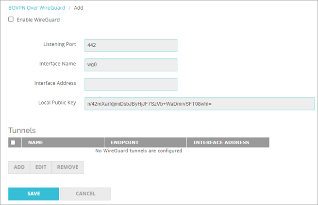
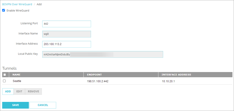
The Firebox generates a local public key for the WireGuard interface. You paste this key into the peer configuration on the remote Firebox when you configure a tunnel to this Firebox. Make sure that the peer endpoint is reachable and that UDP traffic on the configured port is allowed.
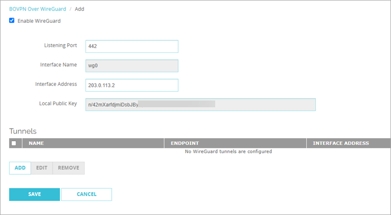
- Select the Enable WireGuard check box.
The Interface Name text box shows the WireGuard interface name (for example, wg0). Fireware assigns this name automatically. - In the Listening Port text box, type the UDP port for WireGuard. The default port is 442.
- In the Interface Address text box, type the IP address assigned to the local WireGuard interface.
- Click Save.
Configure a Tunnel to a WireGuard Peer
- In the Tunnels section, click Add.
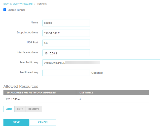
The Tunnels settings page opens. - Select the Enable Tunnel check box.
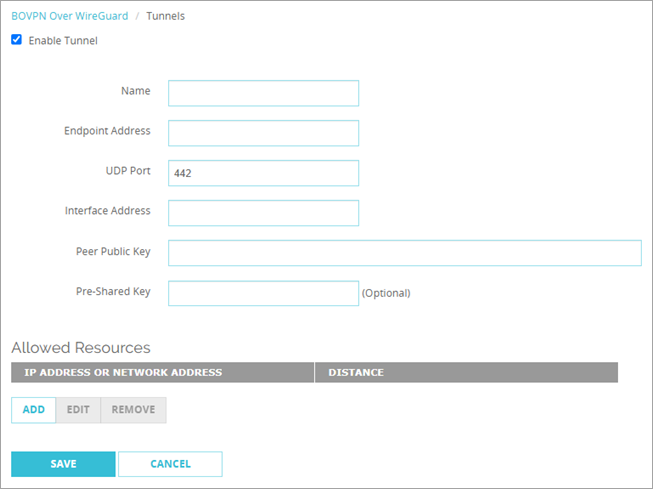
- In the Name text box, type a name for the tunnel to the peer. The name must be unique among tunnel names, Mobile VPN group names, and interface names.
- In the Endpoint Address text box, type the IP address or domain name of the peer Firebox.
- In the UDP Port text box, type the listening port of the remote Firebox. The default port is 442.
- In the Interface Address text box, type the WireGuard interface address of the peer Firebox.
- In the Peer Public Key text box, type the public key from the remote Firebox for this peer tunnel.
- (Optional) In the Pre-Shared Key text box, type a WireGuard pre-shared key. Use the same pre-shared key on both Fireboxes.
The WireGuard pre-shared key is a base64-encoded 32-byte random value that is exactly 44 ASCII characters in length.
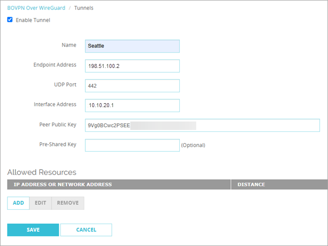
- In the Allowed Resources section, click Add. Allowed resources define the networks that can communicate through the tunnel. The Firebox adds these networks to the routing table for the WireGuard interface. You must add at least one allowed resource before you save a new tunnel.
The Allowed Resources dialog box opens.
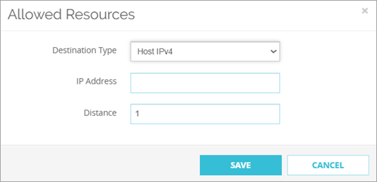
- From the Destination Type drop-down list, select Host IPv4 or Network IPv4.
- In the IP Address text box, type a host IP address or network IP address.
- In the Distance text box, type a value from 1 through 254. Distance specifies the route preference for an allowed resource. When multiple routes exist to the same destination, the Firebox uses the route with the lowest distance value.
- Click Save.
The Allowed Resources list shows the new resource.
- Click Save.
The tunnel to the peer shows in the Tunnels list.
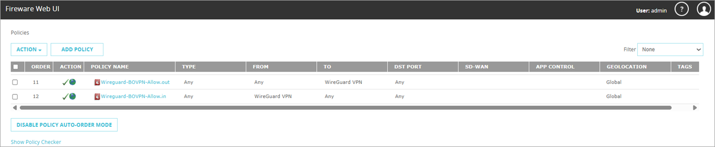
When you save the configuration, the Firebox adds the WireGuard-BOVPN-Allow.in and WireGuard-BOVPN-Allow.out policies to allow traffic between local and remote networks.
Before you can create a WireGuard tunnel with Policy Manager, you must first connect to the Firebox to retrieve the local public key.
- Select File > Open > Firebox.
The Fireware Policy Manager dialog box opens.
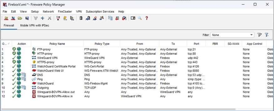
- Click Yes, then save the configuration file.
The Open Firebox dialog box opens.
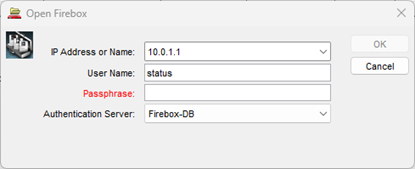
- In the Passphrase text box, type the passphrase for the status user, then click OK.
- Select VPN > BOVPN over WireGuard.The WireGuard configuration dialog box opens.
- The Interface Name text box shows the WireGuard interface name (for example, wg0). Fireware assigns this name automatically.
- You paste the Local Public Key that appears here into the peer configuration on the remote Firebox when you configure a tunnel to this Firebox.
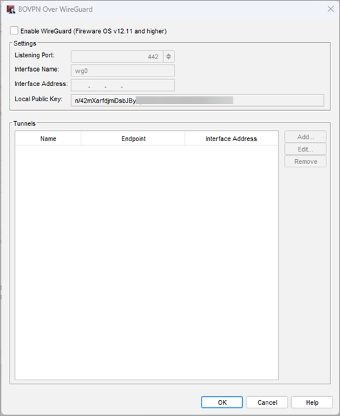
- Select the Enable WireGuard check box.
- In the Listening Port text box, type the UDP port for WireGuard. The default port is 442.
- In the Interface Address text box, type the IP address assigned to the local WireGuard interface.
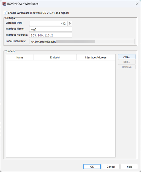
Configure a Tunnel to a WireGuard Peer
Make sure that the peer endpoint is reachable and that UDP traffic on the configured port is allowed.
- In the Tunnels section, click Add.
The Tunnel dialog box opens. - Select the Enable Tunnel check box.
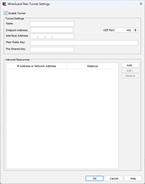
- In the Name text box, type a name for the tunnel to the peer. The name must be unique among tunnel names, Mobile VPN group names, and interface names.
- In the Endpoint Address text box, type the IP address or domain name of the peer Firebox.
- In the UDP Port text box, type the listening port of the remote Firebox. The default port is 442.
- In the Interface Address text box, type the WireGuard interface address of the peer Firebox.
- In the Public Key text box, type the public key from the remote Firebox for this peer tunnel.
- (Optional) In the Pre-Shared Key text box, type a WireGuard preshared key. Use the same pre-shared key on both Fireboxes.
The WireGuard pre-shared key is a base64-encoded 32-byte random value that is exactly 44 ASCII characters in length.
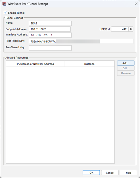
- In the Allowed Resources section, click Add. Allowed resources define the networks that can communicate through the tunnel. The Firebox adds these resources to the routing table for the WireGuard interface. You must add at least one allowed resource before you can save a new tunnel.
The Add Route dialog box opens.
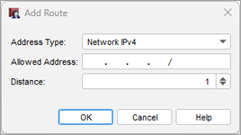
- From the Address Type drop-down list, select Host IPv4 or Network IPv4.
- In the Allowed Address text box, type the host IP address or network IP address.
- In the Distance text box, type a value from 1 through 254. Distance specifies the route preference for an allowed resource. When multiple routes exist to the same destination, the Firebox uses the route with the lowest distance value.

- Click OK.
The Allowed Resources list shows the new resource.

- Click OK.
The tunnel to the peer shows in the Tunnels list.

- To close the BOVPN over WireGuard dialog box, click OK.
- Save the configuration to the Firebox.
When you save the configuration to the Firebox, the Firebox adds the WireGuard-BOVPN-Allow.in and WireGuard-BOVPN-Allow.out policies to allow traffic between local and remote networks.
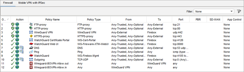
WireGuard establishes communication when you send traffic through the tunnel. You might have to generate traffic before peer status and handshake information appear.
Configure the Tunnel on the Peer Firebox
Repeat the tunnel configuration on the peer Firebox. Use the Site A and Site B example values in the Before You Begin section as a guide:
- Enable WireGuard and configure a unique Interface Address for the local WireGuard interface.
- Use the public key from the first Firebox as the peer public key.
- Configure the endpoint address and UDP listening port of the first Firebox.
- Configure the Peer Interface Address with the WireGuard Interface Address of the first Firebox. This address must be in a different network from the local WireGuard Interface Address.
- Configure allowed resources for the private networks behind the first Firebox (the remote networks from this Firebox).
- If you use a pre-shared key, use the same pre-shared key on both Fireboxes.
After you configure the tunnel on both Fireboxes, send traffic between the networks included in the allowed resources to initiate the tunnel. For more information about how to monitor BOVPN status and traffic, go to Monitor BOVPN over WireGuard.
Edit or Delete a Tunnel
To add or edit an allowed resource for update tunnel settings for an existing tunnel, you can edit the tunnel settings. You can also delete tunnels.
- Select VPN > BOVPN Over WireGuard.
The BOVPN over WireGuard page opens. - Select the tunnel from the Tunnels list and click Edit.
The tunnel settings page opens. - Make the changes, then click Save.
- To delete a tunnel, select the tunnel from the Tunnels list and click Remove.
- Select VPN > BOVPN Over WireGuard.
The BOVPN Over WireGuard dialog box opens. - Select the tunnel from the Tunnels list and click Edit.
The Tunnel dialog box opens. - Make the changes, then click OK.
- To delete a tunnel, select the tunnel from the Tunnels list and click Remove.
- To close the WireGuard VPN dialog box, click OK.
- Save the configuration to the Firebox.
Verify the WireGuard Tunnel
After you complete the configuration on both Fireboxes, verify that the tunnel is established and routes traffic as expected.
- Verify that the peer status shows that the tunnel is established, or that the Last Handshake Time shows a recent handshake.
- Verify that routes for the configured allowed resources show in the routing table. To view routes, select System Status > Routes. For more information, go to Read the Firebox Route Tables.
- Send traffic between computers on the local and remote networks that are included in the allowed resources to initiate and test the tunnel.
- Verify that traffic reaches the remote network and that return traffic reaches the local network.
- Review Firebox log messages for denied traffic, routing issues, or WireGuard handshake errors if connectivity fails. For more information, go to Read a Log Message.
For detailed instructions, go to Monitor BOVPN over WireGuard.