BOVPN Virtual Interface with Dynamic Routing
Applies To: Locally-managed Fireboxes
You can use a BOVPN virtual interface to enable the Firebox to use dynamic routing to find the routes to private networks on a peer Firebox, or on a third-party endpoint, through the VPN tunnel. When you use dynamic routing with a BOVPN virtual interface, the device at each end of the tunnel automatically learns the routes to networks advertised by the other gateway.
Example
This example shows dynamic routing between a Firebox at Site A and a Firebox at Site B. The sites use OSPF to dynamically update routes through the BOVPN virtual interface.
For examples that show BGP dynamic routing between a Firebox and a third-party cloud endpoint, go to:
- BOVPN Virtual Interface for Dynamic Routing to Microsoft Azure
- BOVPN Virtual Interface for Dynamic Routing to Amazon Web Services (AWS)
BGP is supported for BOVPN virtual interface connections to Microsoft Azure and Amazon AWS. OSPF is not supported.
Site A Firebox
For this example, the Site A Firebox has two external interfaces, one trusted network, and four optional networks.
| Interface | Type | Name | IP Address |
|---|---|---|---|
| 0 | External | External | 203.0.113.2/24 |
| 1 | Trusted | Trusted | 10.0.1.1/24 |
| 2 | Optional | Optional-1 | 10.0.2.1/24 |
| 3 | Optional | Optional-2 | 10.0.3.1/24 |
| 4 | Optional | Optional-3 | 10.0.4.1/24 |
| 5 | Optional | Optional-4 | 10.0.5.1/24 |
| 6 | External | External-2 | 190.0.2.2/24 |
The administrator at Site A wants to propagate routes for the Trusted, Optional-1, and Optional-2 networks through the BOVPN tunnel, but does not want to propagate routes for the Optional-3 and Optional-4 networks.
Site B Firebox
For this example, the Site B Firebox has one external interface, one trusted network, and three optional networks.
| Interface | Type | Name | IP Address |
|---|---|---|---|
| 0 | External | External | 198.51.100.2/24 |
| 1 | Trusted | Trusted | 10.50.1.1/24 |
| 2 | Optional | Optional-1 | 10.50.2.1/24 |
| 3 | Optional | Optional-2 | 10.50.3.1/24 |
| 4 | Optional | Optional-3 | 10.50.4.1/24 |
The administrator at Site B wants to propagate routes for the Trusted and Optional-1 networks through the BOVPN tunnel, but does not want to propagate routes for the Optional-2 and Optional-3 networks.
BOVPN Virtual Interface Configuration
The BOVPN virtual interface on each Firebox must be configured to use the same settings. For this example, we assume that Site A and Site B agree to use a pre-shared key and to use these IP addresses for the BOVPN virtual interface:
- Site A BOVPN virtual interface local IP address — 10.1.1.1
- Site B BOVPN virtual interface local IP address — 10.2.2.2
All other BOVPN virtual interface settings keep the default values.
Site A BOVPN Virtual Interface Configuration
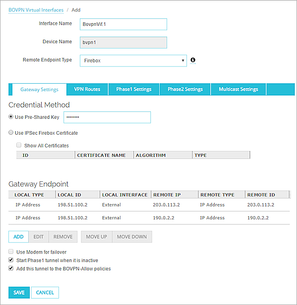
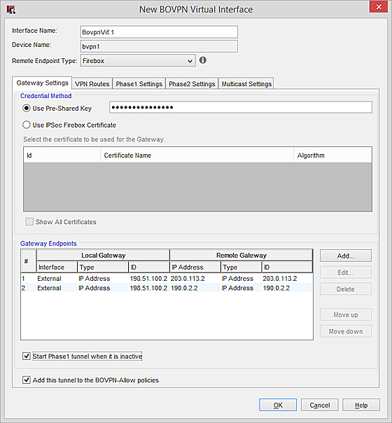
On the Gateway Settings tab of the BOVPN virtual interface configuration, specify these settings:
-
- The Credential Method is the pre-shared key the two sites agreed upon.
- The Gateway Endpoints list includes two gateway endpoint pairs, one for each external interface at Site A.
- First gateway endpoint pair:
Local Gateway — 203.0.113.2 (the IP address of the first external interface on the Site A Firebox)
Remote Gateway — 198.51.100.2 (the external interface IP address of the Site B Firebox) - Second gateway endpoint pair:
Local Gateway — 190.0.2.2 (the IP address of the second external interface on the Site A Firebox)
Remote Gateway — 198.51.100.2 (the external interface IP address of the Site B Firebox)
- First gateway endpoint pair:
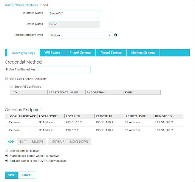
Site A gateway configuration in Fireware Web UI.
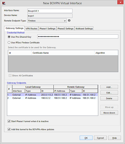
Site A gateway configuration in Policy Manager.
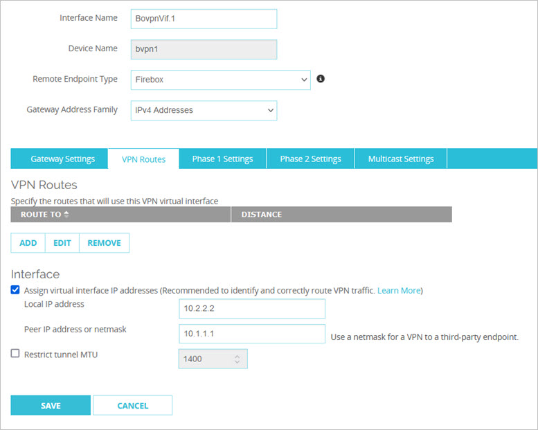
On the VPN Routes tab of the BOVPN virtual interface configuration, specify these settings:
- Assign virtual IP addresses — Enabled
- Local IP address — 10.1.1.1
- Peer IP address — 10.2.2.2
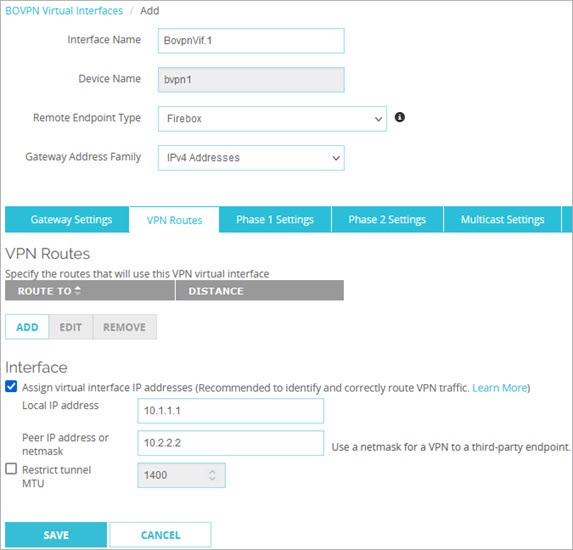
Site A VPN routes in Fireware Web UI.
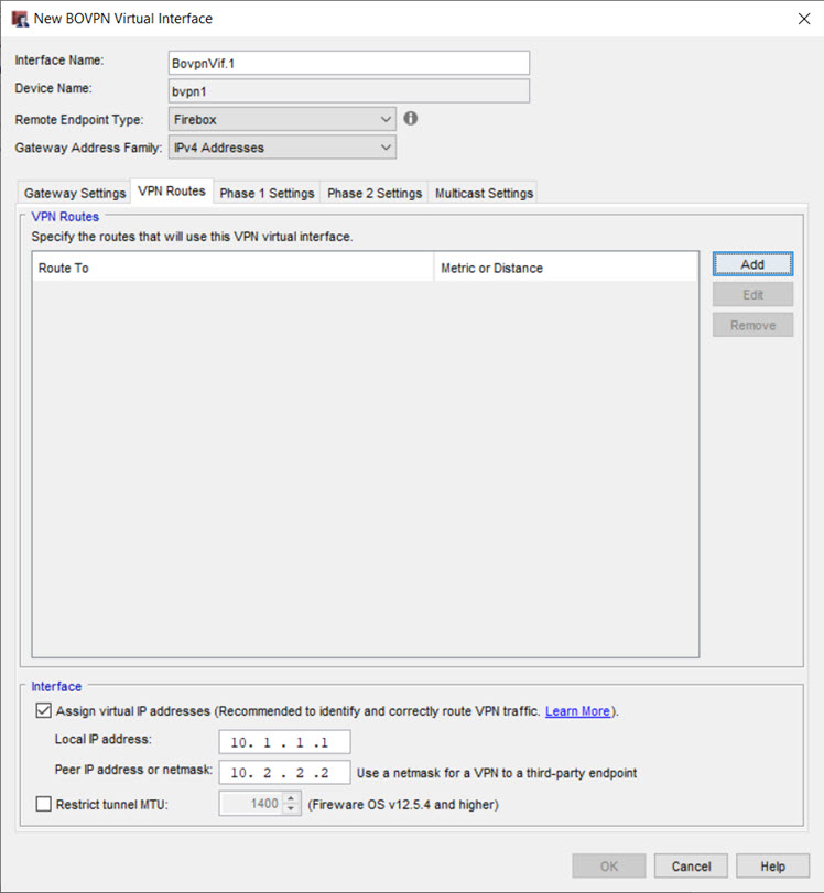
Site A VPN routes in Policy Manager.
Site B BOVPN Virtual Interface Configuration
The configuration at Site B is exactly the same as at Site A, but the local and remote gateway IP addresses are reversed, and the local and peer IP addresses are reversed.
On the Gateway Settings tab of the BOVPN virtual interface configuration, specify these settings:
- From the Remote Endpoint Type drop-down list, select Firebox. This option uses the GRE protocol to encapsulate the IPSec tunnel.
- The Credential Method uses the pre-shared key the two sites agreed upon.
- The Gateway Endpoints list includes two gateway endpoint pairs, one for each external interface at Site A.
- First gateway endpoint pair:
Local Gateway — 198.51.100.2 (the external interface IP address of the Site B Firebox)
Remote Gateway — 203.0.113.2 (the IP address of the first external interface on the Site A Firebox) - Second gateway endpoint pair:
Local Gateway — 198.51.100.2 (the external interface IP address of the Site B Firebox)
Remote Gateway — 190.0.2.2 (the IP address of the second external interface on the Site A Firebox)
- First gateway endpoint pair:
Site B gateway configuration in Fireware Web UI.
Site B gateway configuration in Policy Manager.
On the VPN Routes tab of the BOVPN virtual interface configuration, specify these settings:
- Assign virtual IP addresses — Enabled
- Local IP address — 10.2.2.2
- Peer IP address — 10.1.1.1
Site B VPN routes in Fireware Web UI.

Site B VPN routes in Policy Manager.
Dynamic Routing Configuration
After you define virtual interface IP addresses, you can use them in the dynamic routing configuration.
In the OSPF configuration:
- Select the Peer IP address in the BOVPN virtual interface configuration to refer to the peer-to-peer network.
- Select the Device Name (bvpn1) in the BOVPN virtual interface configuration to refer to the BOVPN interface.
In this example configuration, Site A propagates routes for the Trusted, Optional-1 and Optional-2 local networks. Site B propagates routes for the Trusted and Optional-1 local networks.
This example shows two options to configure OSPF on each Firebox.
Specify the OSPF passive-interface command to configure the bvpn1 interface as the only active interface. Then specify the OSPF network command to select which networks to advertise.
Site A OSPF configuration:
router ospf
! Exclude all but bvpn interfaces
passive-interface default
no passive-interface bvpn1
! which networks to announce in OSPF area 0.0.0.0
! bvpn point-to-point networks - You must type the peer IP address for Site B 10.2.2.2/32 that you specified in the Site A BOVPN virtual interface configuration
network 10.2.2.2/32 area 0.0.0.0
! trusted network
network 10.0.1.0/24 area 0.0.0.0
! optional networks
network 10.0.2.0/24 area 0.0.0.0
network 10.0.3.0/24 area 0.0.0.0
Site B OSPF configuration:
router ospf
! Exclude all but bvpn interfaces
passive-interface default
no passive-interface bvpn1
! which networks to announce in OSPF area 0.0.0.0
! bvpn point-to-point network - You must type the peer IP address for Site A 10.1.1.1/32 that you specified in the Site B BOVPN virtual interface configuration
network 10.1.1.1/32 area 0.0.0.0
! trusted network
network 10.50.1.0/24 area 0.0.0.0
! optional network
network 10.50.2.0/24 area 0.0.0.0
You must specify the peer IP address for each site. If you do not specify the peer IP address, the routers will assign an arbitrary IP address for the device and the VPN will not work correctly.
Specify the OSPF access-list and redistribute commands to select the connected networks you want to redistribute.
Site A OSPF configuration:
! filter the connected networks to propagate
access-list ospf_filter permit 10.0.1.0/24
access-list ospf_filter permit 10.0.2.0/24
access-list ospf_filter permit 10.0.3.0/24
access-list ospf_filter deny any
! redistribute the routes
route-map ospf_redis permit 10
match ip address ospf_filter
! bvpn point-to-point network - You must type the peer IP address for Site B 10.2.2.2/32 that you specified in the Site A BOVPN virtual interface configuration
interface bvpn1
router ospf
redistribute connected route-map ospf_redis
network 10.2.2.2/32 area 0.0.0.0
Site B OSPF configuration:
! filter the connected networks to propagate
access-list ospf_filter permit 10.50.1.0/24
access-list ospf_filter permit 10.50.2.0/24
access-list ospf_filter deny any
! redistribute the routes
route-map ospf_redis permit 10
match ip address ospf_filter
! bvpn point-to-point network - You must type the peer IP address for Site A 10.1.1.1/32 that you specified in the Site B BOVPN virtual interface configuration
interface bvpn1
router ospf
redistribute connected route-map ospf_redis
network 10.1.1.1/32 area 0.0.0.0
You must specify the peer IP address for each site. If you do not specify the peer IP address, the routers will assign an arbitrary IP address for the device and the VPN will not work correctly.
To enable each Firebox to redistribute static routes, you can also specify the redistribute static command. This is not necessary in this example, because all of the networks we want to propagate are directly connected to each Firebox.
After the configuration files are saved to the Fireboxes at Site A and Site B, the BOVPN tunnel is active and dynamic routes are propagated through the tunnel.
See Dynamic Network Routes
After the BOVPN tunnel is established, each Firebox uses OSPF to find the routes to the connected networks propagated by the peer device.
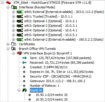
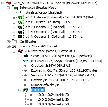
You can see these routes in WatchGuard System Manager and Firebox System Manager when you expand the BOVPN virtual interface for each Firebox.
For the Firebox at Site A, Firebox System Manager shows two entries in the Route to section. These correspond to the two private networks that were specified in the Site B OSPF configuration.
10.50.1.0/24 metric 20
10.50.2.0/24 metric 20
For the Firebox at Site B, Firebox System Manager shows three entries in the Route to section. These correspond to the three private networks that were specified in the Site A OSPF configuration.
10.0.1.0/24 metric 20
10.0.2.0/24 metric 20
10.0.3.0/24 metric 20
On the Firebox System Manager Status Report tab, the dynamic network routes appear in the IPv4 Routes section. For more information about the route table, go to Read the Firebox Route Tables.
In Fireware Web UI, the learned network routes appear in the route table for each Firebox. To see the routes, select System Status > Routes. For more information about the routes table in Fireware Web UI, go to Routes.
The interface name for routes that use the BOVPN virtual interface is the Device Name that is automatically assigned when you create the BOVPN virtual interface. The name of the first BOVPN virtual interface is bvpn1.
For this example, the routes that use the bvpn1 interface at Site A are:
| Destination | Interface | Gateway | Description |
|---|---|---|---|
| 10.2.2.2 | bvpn1 | 0.0.0.0 | The virtual BOVPN interface peer IP address |
| 10.50.1.0 | bvpn1 | 10.2.2.2 | Route learned from Site B |
| 10.50.2.0 | bvpn1 | 10.2.2.2 | Route learned from Site B |
For this example, the routes that use the bvpn1 interface at Site B are:
| Destination | Interface | Gateway | Description |
|---|---|---|---|
| 10.1.1.1 | bvpn1 | 0.0.0.0 | The virtual BOVPN interface peer IP address |
| 10.0.1.0 | bvpn1 | 10.1.1.1 | Route learned from Site A |
| 10.0.2.0 | bvpn1 | 10.1.1.1 | Route learned from Site A |
| 10.0.3.0 | bvpn1 | 10.1.1.1 | Route learned from Site A |
Configure a BOVPN Virtual Interface
Configure IPv4 Routing with OSPF
BOVPN Virtual Interface Examples
BOVPN Virtual Interface for Dynamic Routing to Microsoft Azure
BOVPN Virtual Interface for Dynamic Routing to Amazon Web Services (AWS)