Wireless Network Design
Evaluate Requirements
When you evaluate your current environment and wireless requirements, make sure to consider:
- What wireless modes must your access point support (802.11a/b/g/n, 802.11ac Wave 1, Wave 2)?
- What types of wireless clients do you want to allow to connect?
- What wireless modes do they typically support?
- What SSIDs and networks do you want to create?
- Are there groups of wireless users who need wireless access to different network resources?
- Do you want to set up a guest wireless network that only allows Internet access?
- Where is the best physical location for each AP?
- What is the physical size of the environments wireless users will connect from?
- Do you need more than one AP to cover multiple areas?
Coverage Planning
Traditional coverage planning examines the physical environment where the wireless network will be deployed and the different factors that can affect your wireless signal power, range, and attenuation.
Coverage planning provides:
- Optimal frequency usage and access point locations
- Determination of transmit power levels
- Prevention of channel interference
- Examination of floor plans, physical obstructions, and building materials
Capacity Planning
As part of your wireless deployment planning you must also consider capacity and airtime demand. You must factor in to your plan the expected peak airtime demand amount and type of traffic, and traffic patterns for your wireless network and the coverage area it serves.
For example, a deployment for a hotel and its conference rooms has very different capacity and airtime demand criteria than a deployment for a small office, a retail department store, or a school campus. Each wireless deployment is unique and requires both coverage and capacity planning.
Capacity and airtime demand analysis provides:
- Optimal number of clients per access point radio, including idle and active clients. You must factor in slow periods and worst-case usage scenarios.
- Airtime demand and minimum data rates for different types of application traffic.
- Include email, web, video, social media, streaming, and other applications.
- Determine bandwidth throughput per application and connection, then determine aggregate bandwidth required in the wireless network coverage area.
- Considerations for growth, based on the number of connected clients and application bandwidth usage
Wireless Site Survey
Complete a wireless site survey to analyze your physical environment and existing wireless signals.
Use a wireless site survey utility, such as Ekahau HeatMapper, AirMagnet Planner, or any other similar tool.
- Measure before the deployment as part of your planning
- Measure any existing wireless signals and interference in your environment
- Measure wireless signal strength at different locations.
- Measure after the deployment to see the AP signal strength and range
- After you install your access points, make another heat map to verify that your current placement provides adequate coverage and signal strength.
- Check for wireless channel congestion and make sure the distance between APs does not degrade the signal to problematic levels
Channel Capacity Planning
Most wireless networks are designed for capacity rather than coverage, especially in educational environments where high client densities and high bit rate applications, such as video streaming, are common.
To design networks based on capacity, the first step is to define the requirements, which include client density, client types, applications, use cases, and throughput requirements.
For a successful design, you also need other information related to the environment. This includes factors such as Wi-Fi spectrum availability, building layouts, building materials used, and neighbor Wi-Fi channel usage.
Design Wireless Networks for Capacity
The design process includes these analysis and planning stages:
- Requirements Analysis (Clients, Applications, Use Cases)
- Environment Analysis
- Channel Capacity Planning
Requirements Analysis — Clients
You must determine the number and types of client devices and where they are located on the network. Channel capacity and overall network capacity are as much a function of the client population as the types of APs and switches deployed. While it is not always possible to know the exact breakdown of client capabilities (for example, 802.11n vs. 802.11ac, Wave 1 or Wave 2 802.11ac, 1x1, 2x2, and 3x3) for a given area of the network, the more details that you know, the more accurate your channel capacity planning will be. Often you can use monitoring tools in the current Wi-Fi deployment to gather details about the clients in use on your network.
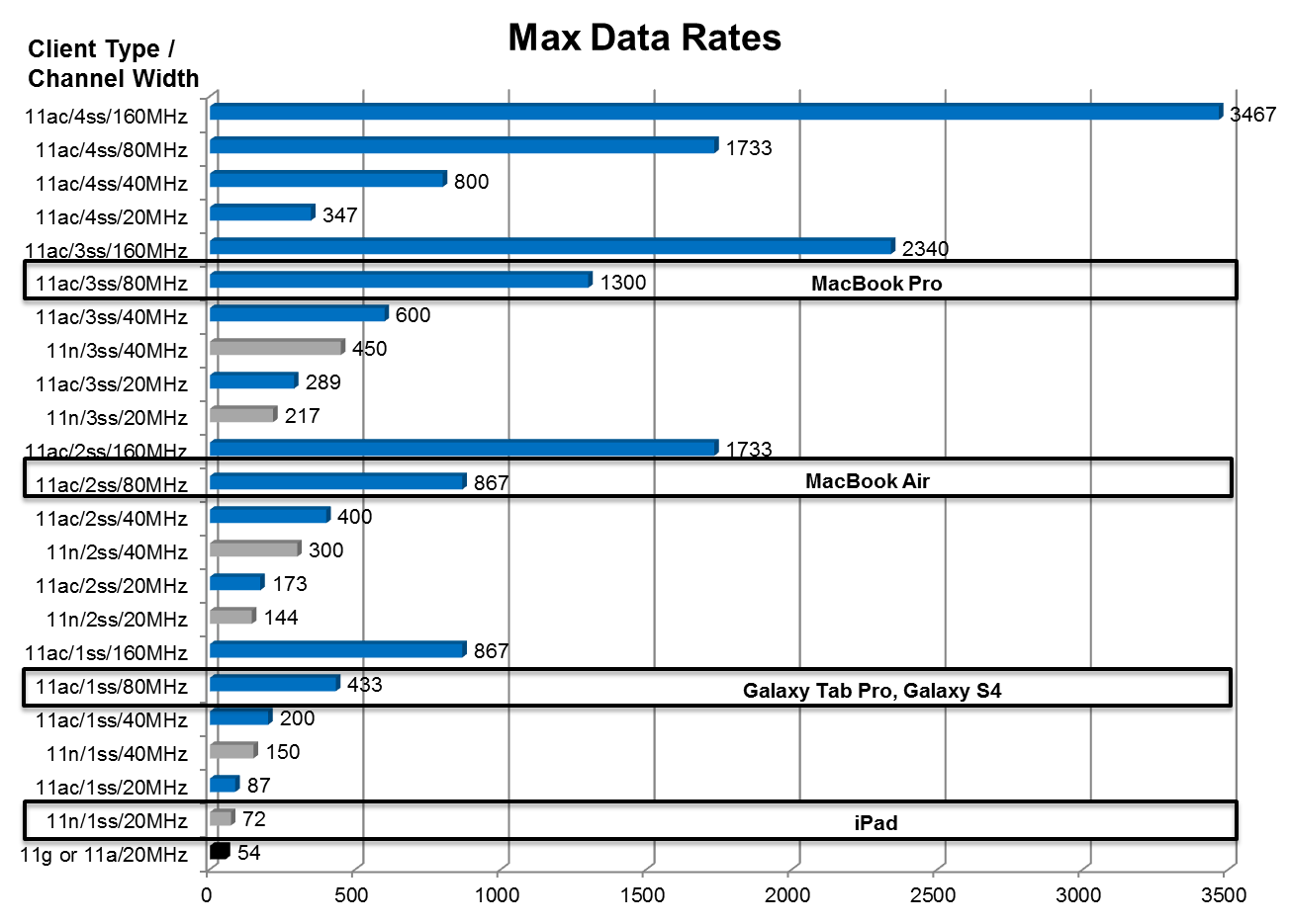
For example, when you compare the maximum data rate of the 1x1 Samsung Galaxy Tab Pro (433 Mbps) to that of the 3x3 Apple MacBook Pro (1.3 Gbps), you can see that the MacBook Pro has approximately three times the maximum data rate of the Galaxy Tab Pro. A wireless network that has only MacBook Pro clients could require as much as three times the capacity of a wireless network with only Galaxy Tab Pro clients.
Requirements Analysis — Applications
You must determine which applications are typically used on your wireless client devices. To estimate a per-client Mbps throughput requirement for a given area of a deployment, use the application with the highest bit rate. For example, in a classroom the highest bit rate application could be HD video streaming at 5 Mbps. For this use case, we recommend a per-client throughput requirement of 5 Mbps. To determine which applications are used by your wireless clients, you can use application visibility tools on your current wireless network.
It is also important to consider the requirements for applications that you plan to use in the future. We recommend you communicate with IT personnel about proposed future application use.
These are reference approximate bit rates for common applications. You can use these values to calculate approximate capacity requirements.
|
Application |
Approximate Average Bit Rate |
|---|---|
|
Audio |
100–1 Mbps |
|
File Backups |
20–60 Mbps |
|
File Sharing |
5 Mbps |
|
On-Line Testing |
2–4 Mbps |
|
Printing |
1–3 Mbps |
|
Video Conferencing: Standard Definition |
5–1 Mbps |
|
Video Conferencing: High Definition |
2–3 Mbps |
|
Video Gaming* |
Requires measurements |
|
Video Streaming: Standard Definition |
1 Mbps |
|
Video Streaming: High Definition 720p |
3–5 Mbps |
|
Video Streaming: High Definition 1080p |
8–12 Mbps |
|
Video Streaming: UHD (4K) |
18–25 Mbps |
|
Webinars |
1 Mbps |
|
Web Browsing |
750 Kbps |
* We recommend that you complete an over-the-air packet capture or use the Application Visibility feature in WatchGuard Wi-Fi Cloud to measure the application bit rate on your current wireless network.
Use Cases
A use case is defined as the number and types of devices and their applications and usage patterns for a specific location. To learn about use cases for a deployment, we recommend you perform a thorough site walk-through with IT personnel familiar with the current network. You can also find solutions for several use cases for a school campus deployment in the Deployment Use Cases section.
Environment Analysis
Wireless Environmental Factors
There are several environmental factors that can affect the range and performance of wireless networks. You must estimate the path loss and attenuation of your wireless signals because of these factors.
Walls and ceilings
Walls and ceilings between the AP and wireless clients can degrade signal strength. Wireless signals can penetrate walls and other structures, but the rate of penetration is directly related to the type of building materials, material thickness, and the distance from the wireless antenna.
Building materials
Metal and aluminum doors, glass, concrete, metal studs, brick walls, glass, and other types of building materials can have a significantly negative effect on the strength of wireless signals.
EMI (Electro-magnetic interference)
EMI from other electrical devices, such as microwaves, cordless phones, and wireless headsets can generate significant RF noise and degrade or disrupt wireless communications.
Distance
Wireless signals degrade quickly past their maximum range. You must plan your network carefully to provide adequate wireless coverage over the range you require in your environment.
Wireless Regulatory Domain
The number of channels potentially available for a deployment depends on the regulatory domain where the deployment is located. Some regulatory domains have greater spectrum capacity than others. The amount of spectrum available for a given deployment has a direct impact on the types of uses cases you can support.
RF Environment
You must assess the RF (radio frequency) environment to identify local sources of Wi-Fi and non-WiFi interference. For example, RF environments for schools located in dense urban areas have a higher potential interference than for schools located in rural areas.
Channel Capacity Planning
As part of capacity planning you must review and understand the wireless spectrum availability to help guide the planning process.
Spectrum Availability in 5 GHz
This diagram describes the current and proposed spectrum for the regulatory regions covered by the FCC (Federal Communications Committee) in the United States.
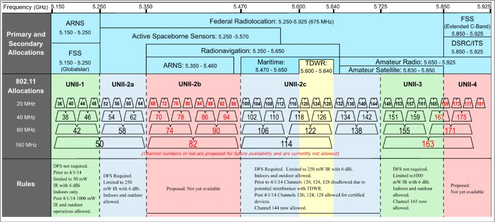
FCC 5 GHz Frequency Allocation. Source: wlanpros.com
All spectrum is currently available in FCC regions except for the frequencies displayed in pink. These frequencies are not currently available, but may be available to the Wi-Fi spectrum in the future. Even if you use all channels currently available, including DFS (Dynamic Frequency Selection) channels, it can be a challenge to meet the capacity requirements of some high density and high throughput use cases.
This table shows the number of channels available for the 5 GHz band in the US.
|
Channel Width |
Without DFS |
With DFS |
|---|---|---|
|
20 MHz |
9 |
25 |
|
40 MHz |
4 |
12 |
|
80 MHz |
2 |
6 |
|
160 or 80+80 MHz |
1 |
3 |
Most networks deploy 40 MHz or 80 MHz channels based on use case requirements and spectrum availability. Some notable exceptions are high density auditorium or stadium and arena deployments where it is often preferable to use 20 MHz channels because of the ability to reuse channels. We recommend you consider the use of 80 MHz channel plans only if DFS channels are available, because without DFS channels only two non-overlapping 80 MHz channels are available. if you use DFS channels, you have six non-overlapping DFS channels available.
802.11ac Wave 1 and Wave 2
This table provides a high-level comparison between the 802.11ac Wave 1 and Wave 2 standards.
|
Feature |
Wave 1 |
Wave 2 |
|---|---|---|
|
Channel Width |
20, 40, 80 |
20, 40, 80, 80+80, 160 MHz |
|
QAM Encoding |
16, 64, 256 QAM |
16, 64, 256 QAM |
|
Spatial Streams |
3 |
4 (as implemented) Up to 8 (per the standard) |
|
Explicit Beamforming |
Some Wave 1 APs |
All Wave 2 APs |
|
MIMO |
SU-MIMO |
SU-MIMO, MU-MIMO |
|
Frame Aggregation |
A-MSDU size 11,426 Bytes A-MPDU size 1,048,576 Bytes |
A-MSDU size 11,426 Bytes A-MPDU size 1,048,576 Bytes |
|
Bands Supported |
5 GHz |
5 GHz |
|
Forward Error Correction |
BCC (Binary Convolutional Code) LDPC (Low Density Parity Check) |
BCC (Binary Convolutional Code) LDPC (Low Density Parity Check) |
|
Dynamic Channel Width |
Some Wave 1 APs |
Most Wave 2 APs |
MU-MIMO
MU-MIMO (Multi-User MIMO) can improve performance in several use cases because of its ability to enable simultaneous transmissions from APs to clients. In regular 802.11 communications, AP-to-client transmissions are serial communications. With MU-MIMO, up to four AP-to-client transmissions can occur simultaneously, which can significantly improve performance and capacity in many use cases.
The boost in performance and capacity depends on several factors, such as channel conditions, client density, client capability, and client mix (SU-MIMO to MU-MIMO ratio). Early MU-MIMO performance testing has shown that when conditions are optimal, aggregate throughput performance can improve by as much as 50%.
The MU-MIMO solution may be able to support HD video, while the Wave 1 solution may only be able to support standard definition video.
MU-MIMO helps in deployments with high-density areas such as auditoriums and classrooms where aggregate throughput demands can be high. Both of these use cases primarily support 1x1 and 2x2 clients. These types of clients are well suited to take advantage of MU-MIMO. Both APs and clients must support Wave 2 to realize the benefits of MU-MIMO.
The WatchGuard AP420 is a high-powered 802.11ac Wave 2 access point, and supports up to four spatial streams in both SU-MIMO and MU-MIMO modes. Earlier generations of Wave 2 APs support up to three spatial streams in MU-MIMO mode. The additional spatial stream for MU-MIMO with the AP420 helps improve wireless network performance and capacity. The AP420 simultaneously supports up to 64 MU-MIMO clients that are dynamically combined for optimal MU-MIMO transmissions of up to 4 MU-MIMO clients at a time.
The AP420 is the recommended platform for most large environments, such as classrooms, cafeterias, auditoriums, libraries, and lecture halls.
DFS Channels
In the past, wireless network designers were reluctant to deploy DFS channels because of concerns about lack of client support and network instability caused by radar event detection. However, many networks today rely on DFS channels to meet higher scalability requirements. Because radar events are not as common as once thought (for most deployments), and newer Wi-Fi devices support DFS channels, DFS-enabled wireless networks are now more common.
We recommend you enable DFS channels if they are available, and that you provision both 5 GHz and 2.4 GHz bands. You can also enable 2.4 GHz coverage throughout the deployment as a best practice to provide access for clients that use both bands.
Channel Width Selection
Wider channel widths such as 80 MHz and 160 MHz provide greater bandwidth and data rates compared to smaller channel widths (20 and 40 MHz), but this also means fewer channels are available and increases the possibility of co-channel interference in dense environments.
For example:
- 160 MHz — Only two channels are available
- 80 MHz — Provides 6 non-overlapping channels if DFS channels available
- 40 MHz — Provides 12 non-overlapping channels if DFS channels available
- 20 MHz — Many channels and combinations available
Channel width selection depends on several factors including use case requirements, spectrum availability, RF environment, and budget for the number of APs required. In a deployment in which you cannot use DFS channels (and must therefore use 40 Mhz channels), you might need to reconsider your requirements. For example, you might need to decrease the bit rate at which video is streamed for 2.4GHz-only clients and for dual band clients that do not support DFS channels. Deploy 2.4 GHz throughout your network to provide some additional capacity.
In general, these channel widths are recommended:
- High density and non-DFS deployments — Use 20 or 40 MHz channels
- Low density and DFS channels available — Use 40 MHz channels
- Well-designed deployment with DFS channels available — 80 MHz channels
Estimate Channel Capacity
Capacity planning must be use-case specific and must consider these factors:
- Total active devices
- Types of devices
- Usage patterns
- Applications in use
- Area of coverage
Estimated throughput capacities for different channel widths and spatial streams are provided in this table, which you can use as a point of reference.
|
Maximum Data Rates |
||||
|---|---|---|---|---|
|
|
20 MHz |
40 MHz |
80 MHz |
160 MHz |
|
1 Spatial Stream |
87 Mbps |
200 Mbps |
433 Mbps |
867 Mbps |
|
2 Spatial Streams |
173 Mbps |
400 Mbps |
867 Mbps |
1.73 Gbps |
|
3 Spatial Streams |
289 Mbps |
600 Mbps |
1.33 Gbps |
2.34 Gbps |
|
4 Spatial Streams |
347 Mbps |
800 Mbps |
1.73 Gbps |
3.47 Gbps |
These rates are maximum data rates and not throughput capacity rates. Throughput capacity rates are much lower because of factors such as protocol overhead, contention loss, and loss due to signal strength degradation.
See Channel Capacity Estimates for a series of tables that estimate channel capacities for different rates of contention loss and loss caused by signal strength degradation for different channel widths and spatial streams. You can reference these tables to simplify the channel capacity planning process.
Channel Capacity Estimate Considerations
The channel throughput capacity estimates provided here and in Channel Capacity Estimates are derived from single AP and multi-AP competitive performance testing. The estimations factor in contention loss seen in tests for 5, 10, 20, 30, 40, 50 and 60 clients per radio where all clients are located within 20 feet (6.096 meters) of the AP under test.
To estimate loss caused by rate adaptation because of lower signal strength, clients are placed from 10 to 60 feet (3.048 – 15.24 meters) away from an AP.
While capacity loss from wireless interference such as co-channel interference (CCI) and adjacent channel interference (ACI) can be substantial, it is not factored into this test data.
This table shows the maximum throughput rates for different channel widths and spatial streams estimated to be 60% of the maximum data rate. This is a conservative number. For example, in certain circumstances, a three spatial stream client (for example, a MacBook Pro) connected to a three spatial stream AP configured for 80 MHz can achieve total throughput of 850 Mbps, which is higher than the listed value of 798 Mbps.
|
Estimated Max Throughput Capacity - 60 % Max Data Rate |
||||
|---|---|---|---|---|
|
Client Active |
20 MHz |
40 MHz |
80 MHz |
160 MHz |
|
1 Spatial Stream |
52 Mbps |
120 Mbps |
260 Mbps |
520 Mbps |
|
2 Spatial Streams |
104 Mbps |
240 Mbps |
520 Mbps |
1.04 Gbps |
|
3 Spatial Streams |
173 Mbps |
360 Mbps |
798 Mbps |
1.40 Gbps |
|
4 Spatial Streams |
208 Mbps |
480 Mbps |
1.04 Gbps |
2.08 Gbps |
Actual use cases are unlikely to have a single client active so the table above is useful only as a benchmark to measure AP performance. When you factor in higher client densities common to large deployments, throughput capacity of a radio declines. You can reference the tables in Channel Capacity Estimates for planning examples, as well as for the use cases presented later in this guide.
Channel Capacity Calculations
This section provides a method to manually calculate channel capacity.
To calculate channel capacity, you must:
- Determine the percentage of airtime or channel utilization that an individual client requires to meet a per client throughput requirements for a particular use case.
- Determine the total channel capacity needed to accommodate all clients in the use case.
For example, a use case has 150 MacBook Pros (or other 11ac 3x3 clients) active concurrently. Each client has a throughput requirement of 2 Mbps. DFS channels are not available so we must use a 40 MHz channel plan.
Before you start your calculations, you must know the estimated channel capacity per radio and an estimated density per radio. This information is required to find the estimated channel capacity in Channel Capacity Estimates. This use case will likely fall into the very high client density category as there will be 150 concurrently active clients.
|
Use Case |
Device Type |
Number of Active Devices/Density |
App or Throughput Requirement Bit Rate |
Channel Capacity |
Per Device Airtime / Channel Capacity |
|---|---|---|---|---|---|
|
Library |
MacBook Pro/3ss |
150 / Very High |
2 Mbps |
120 Mbps / |
1.67% |
The very high client density table in Channel Capacity Estimates shows that for 11ac 3x3 client with a 40 MHz channel, the estimated throughput capacity is 120 Mbps. To determine the percentage of airtime or channel utilization an individual client requires to meet a per-client throughput requirement, divide the throughput requirement by the estimated channel capacity and multiply by 100.
- (Application Bit rate or Throughout Requirement) / (Channel Capacity) x 100 = Per Device Airtime
- (2 Mbps / 120 Mbps) x 100 = 1.67%
- Per Device Airtime = 1.67%
You can use this number to calculate the total number of channels/radios required to meet the use case requirements.
|
Use Case |
Device Type |
Number of Active Devices / Density |
Per Device Airtime |
Total Airtime |
Estimated Channels / Radios Required |
|---|---|---|---|---|---|
|
Library |
MacBook Pro/3ss |
150/Very High |
1.67% |
250% |
3 |
You must multiply the per-client airtime required and the total number of clients active concurrently.
- Number of Active Devices x per Device Airtime = Channels/Radios Required
- 150 Active Devices x 1.67% per Device Airtime = 250%
- Estimated Channels/Radios Required = 3 (Rounding up)
Maximum Clients For APs
This table lists the recommended maximum number of associated and active clients for currently available WatchGuard APs.
|
Model |
Description |
Recommended Use |
Maximum Associated Clients |
Recommended Concurrent Active Clients |
|---|---|---|---|---|
|
AP120 (Legacy) |
Dual radio, 802.11ac Wave 1, 2x2, Indoor |
Low density / throughput areas |
254 |
50 |
|
AP320 (Legacy) |
Dual radio, 802.11ac Wave 1, 3x3, Indoor |
Medium density / throughput areas |
254 |
75 |
|
AP322 (Legacy) |
Dual radio, 802.11ac Wave 1, 3x3, Outdoor |
Outdoors |
254 |
75 |
|
AP125 |
Dual radio, 802.11ac Wave 2, 2x2, Indoor |
Low density / throughput areas |
254 |
50 |
|
AP225W |
Tri radio, 802.11ac |
Low to medium density / throughput areas |
254 |
75 |
|
AP327X |
Dual radio, 802.11ac Wave 2, 2x2, Outdoor |
Outdoors |
254 |
75 |
|
AP325 |
Tri radio, 802.11ac Wave 2 , 2x2, Indoor |
Low to medium density / throughput areas |
254 |
75 |
|
AP420 |
Tri radio, 802.11ac Wave 2 , 4x4, Indoor |
High density / throughput areas |
510 |
150 |
Summary of Channel Capacity Planning Recommendations
This table summarizes the channel capacity planning recommendations for wireless networks.
|
Recommendations |
Notes |
|---|---|
|
Design wireless network for capacity. |
|
|
Focus design on specific use cases. |
Use Case = Number of devices + types of devices + set of applications + usage patterns + for a given area. |
|
Use most demanding application (per use case) to determine throughput requirement. |
If application information is unknown, design for a per client throughput requirement of 5 Mbps. |
|
Use current wireless network to determine type and number of devices per use case. |
|
|
Use current wireless network tools to determine application bit rates. |
Alternatively, packet capture tools can be used to determine application bit rates. |
|
Select the correct APs for the use cases. |
Refer to the recommended maximum clients per AP table for AP selection. |
|
Use predictive planning tools to estimate the number of APs required to meet use case throughput requirements. |
|
|
Design for 5 GHz capacity. |
Deploy both 2.4 GHz and 5 GHz pervasively. |
|
Use DFS channels. |
Discover if any DFS channels cause interference with local radar and remove those channels from the potential operating channel pool. |
|
Use 20 or 40 MHz channels. |
If several DFS channels cannot be used, then plan to use 40 MHz channels. |