The objective of this configuration example is to show how an organization with networks at multiple remote sites can connect with two main corporate sites through BOVPN virtual interfaces. In this example, it is important that the remote sites remain connected to both corporate sites at all times. Because a link could disrupt business, the organization wants to add redundancy so remote sites have more than one route to each corporate site. In this example, we use OSPF to configure redundant routes.
This configuration example is provided as a basic guide. Your network environment might require additional configuration settings.
Solution Overview
This configuration example describes two solutions. Both solutions include BOVPN virtual interfaces, dynamic routing with OSPF, and an MPLS line between the main corporate sites. The solutions differ in these ways:
- In Solution A, the MPLS endpoints are on the same subnet. A BOVPN virtual interface between the MPLS endpoints is not required.
- In Solution B, the MPLS endpoints are on different subnets. A BOVPN virtual interface between the MPLS endpoints is included in the configuration. The OSPF configuration includes additional information so the two sites can advertise routes to each other.
To implement and support this configuration on your network, you must understand dynamic routing.
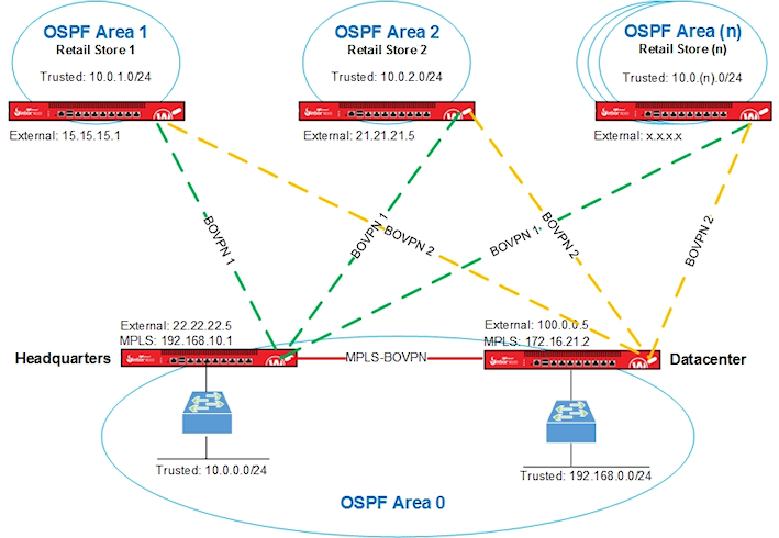
For both solutions in this configuration example, the organization has multiple retail stores with VPN connections to networks at Headquarters and a Datacenter. Headquarters and the Datacenter ares connected by an MPLS link. The OSPF dynamic routing protocol is configured on a Firebox at each site.
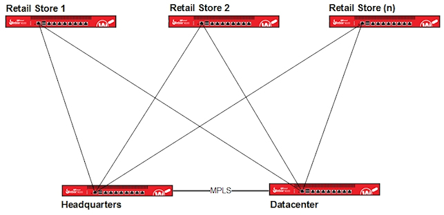
Each store has routes to Headquarters and the Datacenter. Traffic is always routed along the best (lowest cost) route. For example, traffic from Store 1 to Headquarters is normally routed through the VPN tunnel between Store 1 and Headquarters. Traffic from Store 1 to the Datacenter is normally routed through the VPN tunnel between Store 1 to the Datacenter.
If the link between Store 1 and Headquarters becomes unavailable, Store 1 can still access the network at Headquarters after this process occurs:
- OSPF recalculates metrics for routes in its table to find the best route.
- After a brief delay, Store 1 traffic destined for Headquarters is automatically routed along the best route, which is now through the VPN tunnel from Store 1 to the Datacenter, and from the Datacenter to Headquarters.
If the failed link becomes available again, OSPF recalculates metrics and sends traffic along the best route.
Requirements
This configuration example has these requirements:
- Firebox at each site
- BOVPN virtual interfaces configured on each Firebox
- OSPF configured on each Firebox
- MPLS link between Headquarters and the Datacenter without a BOVPN (for Solution A)
- MPLS link between Headquarters and the Datacenter with a BOVPN (for Solution B)
Solution A — How It Works
The next few sections explain the configuration for Solution A:
For an explanation of Solution B, see Solution B Configured Explained.
Network Topology for Solution A
This diagram shows the network topology for Solution A. This solution includes two remote sites and a MPLS connection without a VPN. You can add more remote sites as needed which is indicated by the Firebox at Retail Store (n) in OSPF Area (n).
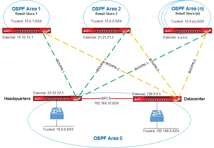
We used these interface IP addresses used in Solution A.
| Firebox Interface | Headquarters | Datacenter | Store 1 | Store 2 |
|---|---|---|---|---|
| External | 22.22.22.5 |
100.0.0.5 | 15.15.15.1 |
21.21.21.5 |
| Trusted |
10.0.0.1 |
192.168.0.1 | 10.0.1.1 | 10.0.2.1 |
| Optional-MPLS | 192.168.10.1 | 192.168.10.2 | n/a | n/a |
VPN Configuration for Solution A
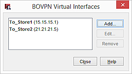
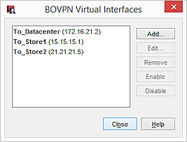
The Firebox at each retail store has two BOVPN virtual interfaces. The interface names indicate the location of the peer Firebox.
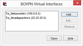
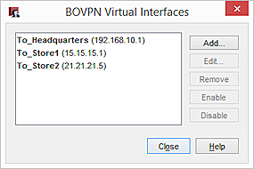
The Fireboxes at Headquarters and the Datacenter also have two BOVPN virtual interfaces:
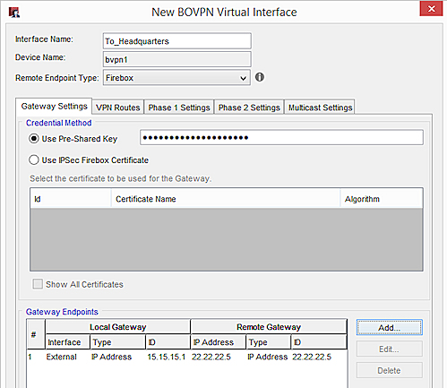
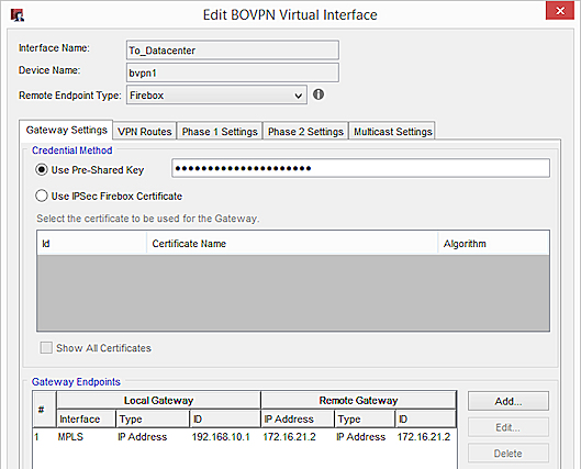
BOVPN Virtual Interface Gateway Settings
On the Gateway Settings tab for each virtual interface, configure these settings:
- Local Gateway ID — IP address of the local external interface
- Interface — Set to External
- Remote Gateway IP Address — IP address of the external interface on the peer Firebox
- Remote Gateway ID — IP address of the external interface on the peer Firebox
Store 1
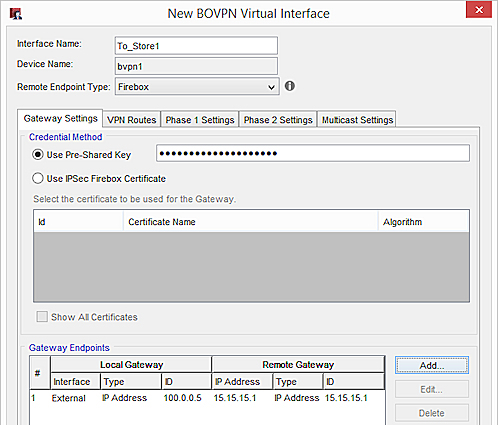
Gateway settings on the Store 1 Firebox for a connection to Headquarters:
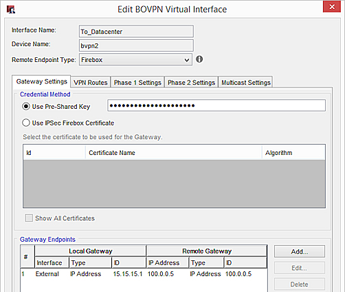
Gateway settings on the Store 1 Firebox for a connection to the Datacenter:
Store 2
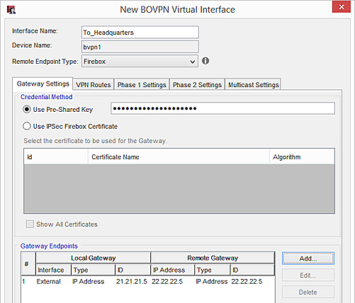
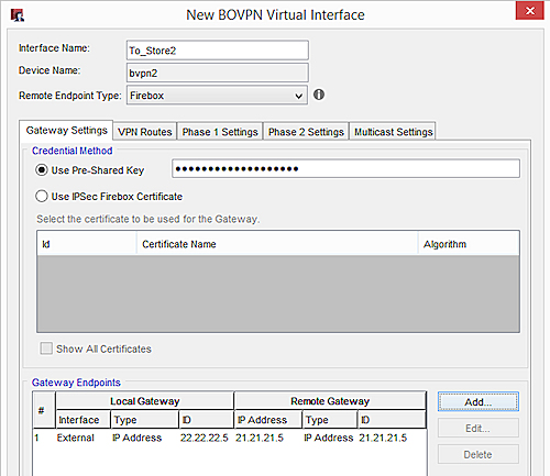
Gateway settings on the Store 2 Firebox for a connection to Headquarters:
Gateway settings on the Store 2 Firebox for a connection to the Datacenter:

Headquarters
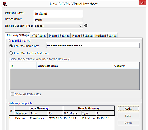
Gateway settings on the Headquarters Firebox for a connection to Store 1:
Gateway Settings on the Headquarters Firebox for a connection to Store 2:
Datacenter
Gateway Settings on the Datacenter Firebox for a connection to Store 1:
Gateway Settings on the Datacenter Firebox for a connection to Store 2:

BOVPN Virtual Interface Phase 1 and 2 Settings
In this example, we recommend these security settings:
Phase 1:
Authentication — SHA-2 (256)
Encryption — AES (256)
Key Group — Diffie-Helman Group 15
Phase 2:
Type — ESP
Authentication— SHA-2 (256)
Encryption— AES (256)
SHA-2 is not supported on XTM
If your XTM device does not support SHA-2, we recommend these settings:
Phase 1:
Authentication — SHA-1
Encryption — AES (256)
Key Group — Diffie-Helman Group 2
Phase 2:
Keep the default proposal, which is ESP-AES-SHA1.
If your MPLS link is a leased line, and you want to avoid the overhead from encryption, we recommend these Phase 2 settings:
Type — ESP
Authentication — SHA-1
Encryption — None
BOVPN Virtual Interface IP Addresses
To configure dynamic routing through a BOVPN virtual interface, you must assign virtual interface IP addresses in the VPN Routes tab.
You can specify any IP addresses that do not conflict with IP addresses already on your network. We recommend that you specify a unique IP address for each virtual interface IP address on your network.
We also recommend that you plan which IP addresses to use in advance. For administrative convenience, we used the third octet of each virtual IP address to indicate the OSPF area number. For example, the third octet in the IP addresses 172.30.1.1 and 172.30.1.2 indicates a VPN tunnel that terminates in Area 1. The third octet in the IP addresses 172.30.2.1 and 172.30.2.2 indicates a VPN tunnel that terminates in Area 2. For more information about OSPF areas, see the OSPF Configuration section.
In our example, we use these virtual IP addresses:
| Firebox Location | Virtual IP Addresses |
|---|---|
| Headquarters |
172.30.1.1 |
| Datacenter |
172.31.1.1 |
| Store 1 | 172.30.1.2 172.31.1.2 |
| Store 2 | 172.30.2.2 172.31.2.2 |
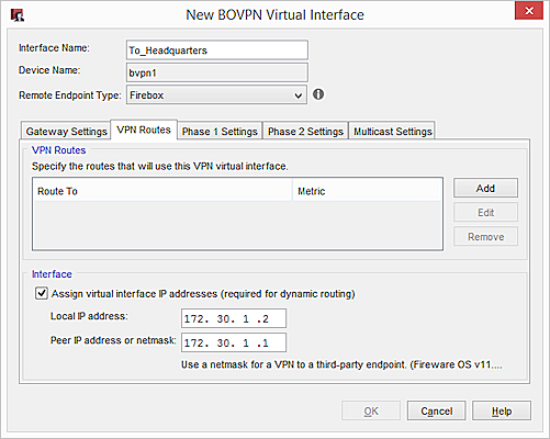
On the VPN Routes tab, these settings are configured:
- Local IP address — The virtual IP address of the local Firebox
- Peer IP address or netmask — The virtual IP address of the peer Firebox
For example, on the Firebox at Store 1, type these IP addresses for a VPN connection to Headquarters:
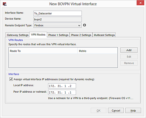
On the Firebox at Store 1, for a connection to the Datacenter:
OSPF Configuration for Solution A
OSPF is enabled on the Firebox at each site. The OSPF configuration includes:
- Routes
- Area definitions
- Route filters
Large networks are typically divided into areas, which are subsets of the OSPF network. Each area has its own number.
To reduce convergence times, and to take advantage of route filters, we recommend that you define OSPF areas. In our example, Area 0 includes both Headquarters and the Datacenter. Each store has its own area, which means Store 1 is in Area 1, and Store 2 is in Area 2.
| Firebox Location | OSPF Area |
|---|---|
| Headquarters | 0 |
| Datacenter | 0 |
| Store 1 | 1 |
| Store 2 | 2 |
To prevent unnecessary route table entries, we recommend that you specify route filters in the OSPF configuration. Your Firebox only advertises routes permitted by the route filter. In our example, route filters in the Headquarters and Datacenter configurations deny advertisements for intra-area routes between retail stores.
For the router-id, specify the virtual IP address of the local Firebox.
For Solution A, the OSPF configurations for each Firebox are as follows.
Store 1
router ospf
ospf router-id 172.30.1.2
!BOVPN to HQ
network 172.30.1.1/32 area 1
!BOVPN to DC
network 172.31.1.1/32 area 1
!Local network
network 10.0.1.0/24 area 1
Store 2
router ospf
ospf router-id 172.30.2.2
!BOVPN to HQ
network 172.30.2.1/32 area 2
!BOVPN to DC
network 172.31.2.1/32 area 2
!Local network
network 10.0.2.0/24 area 2
Headquarters
!Distribute inter-area routes from HQ and DC to Remote
ip prefix-list Central-2-Remote permit 10.0.0.0/24
ip prefix-list Central-2-Remote permit 192.168.10.0/24
ip prefix-list Central-2-Remote permit 192.168.0.0/24
ip prefix-list Central-2-Remote deny any
router ospf
ospf router-id 172.30.1.1
!Internal network area 0
network 10.0.0.0/24 area 0
network 192.168.10.0/24 area 0
!Remote sites individual area
network 172.30.1.2/32 area 1
network 172.30.2.2/32 area 2
!Filter the routes from HQ to remote
area 1 filter-list prefix Central-2-Remote in
area 2 filter-list prefix Central-2-Remote in
Datacenter
!Filter propagated lists
ip prefix-list Central-2-Remote permit 10.0.0.0/24
ip prefix-list Central-2-Remote permit 192.168.0.0/24
ip prefix-list Central-2-Remote permit 192.168.10.0/24
ip prefix-list Central-2-Remote deny any
router ospf
ospf router-id 172.31.1.1
!Add the local network to area 0
network 192.168.0.0/24 area 0
network 192.168.10.0/24 area 0
!VIF sites
network 172.30.1.2/32 area 1
network 172.30.2.2/32 area 2
!Filter the routes from DC to remotes
area 1 filter-list prefix Central-2-Remote in
area 2 filter-list prefix Central-2-Remote in
Solution B — How It Works
The next sections explain the configuration for Solution B:
Network Topology for Solution B
This diagram shows the network topology for Solution B which includes a VPN for the MPLS connection.
In this diagram, we show configuration information for two remote sites. You can add more remote sites as needed which is indicated by "OSPF Area (n)."
We used these interface IP addresses in Solution B.
| Firebox Interface | Headquarters | Datacenter | Store 1 | Store 2 |
|---|---|---|---|---|
| External | 22.22.22.5 |
100.0.0.5 | 15.15.15.1 |
21.21.21.5 |
| Trusted |
10.0.0.1 |
192.168.0.1 | 10.0.1.1 | 10.0.2.1 |
| Optional-MPLS | 192.168.10.1 | 172.16.21.2 | n/a | n/a |
VPN Configuration for Solution B
The Firebox at each retail store has two BOVPN virtual interfaces. The interface names indicate the location of the peer Firebox.
The Firebox at Headquarters has these BOVPN virtual interfaces. Solution B requires a BOVPN between Headquarters and the Datacenter:
The Firebox at the Datacenter has these BOVPN virtual interfaces:
BOVPN Virtual Interface Gateway Settings
On the Gateway Settings tab for each virtual interface, configure these settings:
- Local Gateway ID — IP address of the local external interface
- Interface — Set to External
- Remote Gateway IP Address — IP address of the external interface on the peer Firebox
- Remote Gateway ID — IP address of the external interface on the peer Firebox
Store 1
Gateway settings on the Store 1 Firebox for a connection to Headquarters:
Gateway settings on the Store 1 Firebox for a connection to the Datacenter:
Store 2
Gateway settings on the Store 2 Firebox for a connection to Headquarters:
Gateway settings on the Store 2 Firebox for a connection to the Datacenter:
Headquarters
Gateway settings on the Headquarters Firebox for a connection to Store 1:
Gateway Settings on the Headquarters Firebox for a connection to Store 2:
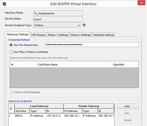
Gateway Settings on the Headquarters Firebox for an MPLS connection the Datacenter:
Datacenter
Gateway Settings on the Datacenter Firebox for a connection to Store 1:
Gateway Settings on the Datacenter Firebox for a connection to Store 2:
Gateway Settings on the Datacenter Firebox for an MPLS connection Headquarters:
BOVPN Virtual Interface Phase 1 and 2 Settings
In our example, we recommend these security settings:
Phase 1:
Authentication — SHA-2 (256)
Encryption — AES (256)
Key Group — Diffie-Helman Group 15
Phase 2:
Type — ESP
Authentication— SHA-2 (256)
Encryption— AES (256)
SHA-2 is not supported on XTM
If your XTM device does not support SHA-2, we recommend these settings:
Phase 1:
Authentication — SHA-1
Encryption — AES (256)
Key Group — Diffie-Helman Group 2
Phase 2:
Keep the default proposal, which is ESP-AES-SHA1.
If your MPLS link is a leased line, and you want to avoid the overhead required for encryption, we recommend these Phase 2 settings:
Type — ESP
Authentication — SHA-1
Encryption — None
BOVPN Virtual Interface IP Addresses
To configure dynamic routing through a BOVPN virtual interface, you must assign virtual interface IP addresses in the VPN Routes tab.
You can specify any IP addresses that do not conflict with IP addresses already on your network. We recommend that you specify a unique IP address for each virtual interface IP address on your network.
We also recommend that you plan which IP addresses to use in advance. For administrative convenience, we used the third octet of each virtual IP address to indicate the OSPF area number. For example, the third octet in the IP addresses 172.30.1.1 and 172.30.1.2 indicates a VPN tunnel that terminates in Area 1. The third octet in the IP addresses 172.30.2.1 and 172.30.2.2 indicates a VPN tunnel that terminates in Area 2. For more information about OSPF areas, see the OSPF Configuration section.
In our example, we use these virtual IP addresses:
| Firebox Location | Virtual IP Addresses |
|---|---|
| Headquarters |
172.30.1.1 |
| Datacenter |
172.31.1.1 |
| Store 1 | 172.30.1.2 172.31.1.2 |
| Store 2 | 172.30.2.2 172.31.2.2 |
On the VPN Routes tab, these settings are configured:
- Local IP address — The virtual IP address of the local Firebox
- Peer IP address or netmask — The virtual IP address of the peer Firebox
For example, on the Firebox at Store 1, type these IP addresses for a VPN connection to Headquarters:
On the Firebox at Store 1, for a connection to the Datacenter:
OSPF Configuration for Solution B
OSPF is enabled on the Firebox at each site. The OSPF configuration includes:
- Routes
- Area definitions
- Route filters
Large networks are typically divided into areas, which are subsets of the OSPF network. Each area has its own number.
To reduce convergence times, and to take advantage of route filters, we recommend that you define OSPF areas. In our example, Area 0 includes both Headquarters and the Datacenter. Each store has its own area, which means Store 1 is in Area 1, and Store 2 is in Area 2.
| Firebox Location | OSPF Area |
|---|---|
| Headquarters | 0 |
| Datacenter | 0 |
| Store 1 | 1 |
| Store 2 | 2 |
To prevent unnecessary route table entries, we recommend that you specify route filters in the OSPF configuration. Your Firebox only advertises routes permitted by the route filter. In our example, route filters in the Headquarters and Datacenter configurations deny advertisements for intra-area routes between retail stores.
For the router-id, specify the virtual IP address of the local Firebox.
For Solution B, the OSPF configuration for the Headquarters and Datacenter Fireboxes has an additional network command. The OSPF configuration for the retail stores is the same as in Solution A.
Store 1
router ospf
ospf router-id 172.30.1.2
!BOVPN to HQ
network 172.30.1.1/32 area 1
!BOVPN to DC
network 172.31.1.1/32 area 1
!Local network
network 10.0.1.0/24 area 1
Store 2
router ospf
ospf router-id 172.30.2.2
!BOVPN to HQ
network 172.30.2.1/32 area 2
!BOVPN to DC
network 172.31.2.1/32 area 2
!Local network
network 10.0.2.0/24 area 2
Headquarters
!Distribute inter-area routes from HQ and DC to Remote
ip prefix-list Central-2-Remote permit 10.0.0.0/24
ip prefix-list Central-2-Remote permit 192.168.0.0/24
ip prefix-list Central-2-Remote deny any
router ospf
ospf router-id 172.30.1.1
!Internal network area 0
network 10.0.0.0/24 area 0
network 192.168.10.0/24 area 0
#To exchange OSPF info with HQ, we must create a BOVPN VIF between the Datacenter and HQ via the interface connected to the MPLS line
#The IP address of this BOVPN VIF is set as (local 172.16.48.1 — peer 172.16.48.2/32)
#Add it to area 0 as well
network 172.16.48.2/32 area 0
!Remote sites individual area
network 172.30.1.2/32 area 1
network 172.30.2.2/32 area 2
!Filter the routes from HQ to remote
area 1 filter-list prefix Central-2-Remote in
area 2 filter-list prefix Central-2-Remote in
Datacenter
!Filter propagated lists
ip prefix-list Central-2-Remote permit 10.0.0.0/24
ip prefix-list Central-2-Remote permit 192.168.0.0/24
ip prefix-list Central-2-Remote deny any
router ospf
ospf router-id 172.31.1.1
!Add the local network to area 0
network 192.168.0.0/24 area 0
network 192.168.10.0/24 area 0
#To exchange OSPF info with HQ, we must create a BOVPN VIF between the Datacenter and HQ via the interface connected to the MPLS line
#The IP address of this BOVPN VIF is set as (local 172.16.48.2 — peer 172.16.48.1/32)
#Add it to area 0 as well
network 172.16.48.1/32 area 0
!VIF sites
network 172.30.1.2/32 area 1
network 172.30.2.2/32 area 2
!Filter the routes from DC to remotes
area 1 filter-list prefix Central-2-Remote in
area 2 filter-list prefix Central-2-Remote in
Conclusion
This configuration example demonstrates how to configure redundant links and OSPF on a large distributed network. This type of configuration provides redundant VPN connections between the remote sites and the main corporate network sites. This example includes two remote sites, but you can add as many remote sites as needed.
This example describes two different solutions. Solution A shows an MPLS connection without a VPN. Solution B shows an MPLS connection with a VPN.
About Open Shortest Path First (OSPF and OSPFv3) Protocol