This integration guide describes how to configure a policy-based Branch Office VPN (BOVPN) tunnel between a WatchGuard Firebox and a Dell SonicWall TZ670.
Integration Summary
The hardware and software used in this guide include:
- Firebox with Fireware v12.11 or higher
- Dell SonicWall TZ670 with SonicOS v7.0.0 or higher
Topology
This diagram shows the topology for a BOVPN connection between a Firebox and a SonicWall TZ670.

Before You Begin
Before you begin these procedures, make sure that:
- If you want to use a cloud-managed Firebox, you have a WatchGuard Cloud account and have added the Firebox to WatchGuard Cloud as a cloud-managed device. You also have configured an external network with the external (public) IP address of the Firebox and at least one internal network on the Firebox.
- If you want to use a locally-managed Firebox, you have configured an external interface with the external (public) IP address of the Firebox and at least one internal network on the Firebox.
- You have configured the external interfaces and zones on the Dell SonicWall TZ670. In this guide, we use the X4 external interface with the 10.10.0.1/24 IP address. For more information about how to configure interfaces, go to the SonicWall User Guide.
Configure the Firebox
You can configure your Firebox for a policy-based BOVPN from WatchGuard Cloud for a cloud-managed Firebox or Fireware Web UI for a locally-managed Firebox.
- Log in to WatchGuard Cloud.
If you log in with a Service Provider account, you must select a Subscriber account from the Account Manager. - From the navigation menu, select Configure > VPNs.
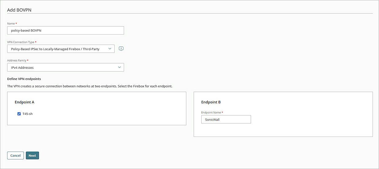
- Click Add BOVPN.
The Add BOVPN page opens. - In the Name text box, type a descriptive name for the BOVPN. In this example, we type policy-based BOVPN.
- From the VPN Connection Type drop-down list, select Policy-Based IPSec to Locally-Managed Firebox / Third-Party.
- From the Address Family drop-down list, select IPv4 Addresses.
- In the Endpoint A section, select your cloud-managed Firebox.
- In the Endpoint B section, in the Endpoint Name text box, type a name to identify the remote VPN endpoint. In our example, we type SonicWall.
- Click Next.
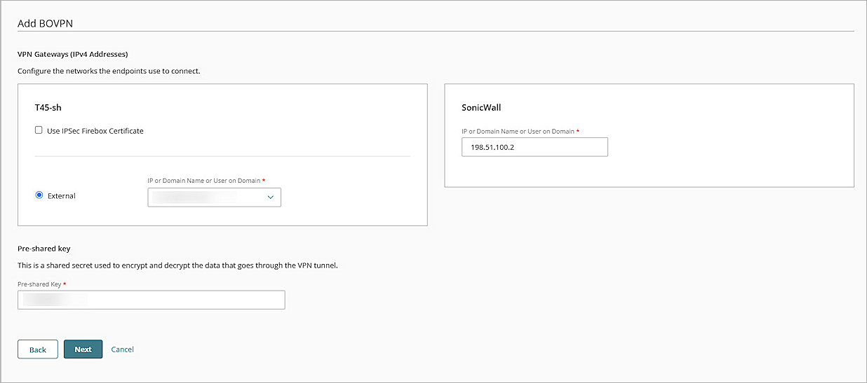
The VPN Gateways settings page opens. - For your cloud-managed Firebox:
- SelectExternal.
- From the IP or Domain Name or User on Domain text box, select an IP address, domain name, or user on domain that resolves to the Firebox external network IP address.
- For the remote VPN endpoint, in the IP or Domain Name or User on Domain text box, type the IP address of your SonicWall WAN interface.
- To encrypt and decrypt the data that goes through the VPN tunnel, in the Pre-Shared Key text box, type a pre-shared key. This pre-shared key matches the pre-shared key you will configure for the IKE Gateway on the SonicWall firewall.
- Click Next.
The Traffic settings page opens. - From the cloud-managed Firebox section, select the internal network that you want to be accessible through the VPN tunnel.
- For the SonicWall VPN endpoint, click Add Network Resource.
- In the Network Resource text box, type the IP address of the private network protected by the SonicWall firewall. In our example, we type 10.10.0.0/24.
- Click Add.
- Keep the default values for all other settings.
- Click Next.
The Tunnel Routes page opens. - Keep the default values for all settings.
- Click Next.
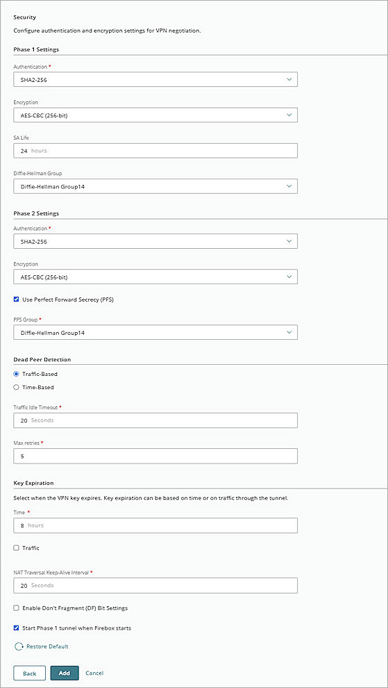
The Security settings page opens. - In the Phase 1 Settings section:
- From the Authentication drop-down list, select SHA2-256.
- From the Encryption drop-down list, select AES-CBC (256-bit).
- In the SA Life text box, type 24.
- From the Diffie-Hellman Group drop-down list, select Diffie-Hellman Group14.
- In the Phase 2 Settings section,:
- From the Authentication drop-down list, select SHA2-256.
- From the Encryption drop-down list, select AES-CBC (256-bit).
- Select the Use Perfect Forward Secrecy (PFS) check box.
- From the PFS Group drop-down list, select Diffie-Hellman Group14.
- Keep all default values for all other settings.
- Click Add.
- (Optional) To open the VPN Configuration Summary page for the cloud-managed Firebox, click View Guide.
- Click Finish.


When you add a BOVPN for a cloud-managed Firebox, WatchGuard Cloud immediately creates and deploys a configuration update for the cloud-managed Firebox.
- Log in to Fireware Web UI at: https://<your Firebox IP address>:8080..
- Select VPN > Branch Office VPN.
The Branch Office VPN configuration page opens. - In the Gateways section, click Add.
The Add page opens. - In the Gateway Name text box, type a name to identify this BOVPN gateway. In this example, we type gateway.1.
- From the Address Family drop-down list, select IPv4 Addresses.
- In the Credential Method section, select Use Pre-Shared Key and in the adjacent text box, type the pre-shared key.
- From the drop-down list, select String-Based .
- In the Gateway Endpoint section, click Add.
The Gateway Endpoint Settings dialog box opens. - From the External Interface drop-down list, select the interface that has the external (public) IP address of the Firebox.
- From the Interface IP Address drop-down list, select Primary Interface IPv4 Address.
The Primary Interface IP Address is the primary IP address you configured on the selected external interface. - For Specify the Gateway ID for Tunnel Authentication, select By IP Address.
- In the adjacent text box, type the primary IP address of the external Firebox interface. In this example, we type 203.0.113.2.
- Select the Remote Gateway tab.
The Remote Gateway page opens. - For Specify the Remote Gateway IP Address for a Tunnel, select Static IP Address.
- In the adjacent text box, type the IP address of your SonicWall WAN connection. In this example, we type 198.51.100.2.
- For Specify the Remote Gateway ID for Tunnel Authentication, select By IP Address.
- In the adjacent text box, type the IP address of your SonicWall WAN connection. In this example, we type 198.51.100.2.
- Keep the default values for all other settings.
- Click OK.
The gateway endpoint you added appears in the Gateway Endpoint section. - In the Gateway Endpoint section, select the Start Phase 1 Tunnel When Firebox Starts check box.
- Select the Phase 1 Settings tab.
The Phase 1 Settings page opens. - From the Version drop-down list, select IKEv2.
- Keep the default values for all other Phase 1 settings.
- Click Save.
The gateway you added appears on the list of gateways. - In the Tunnels section, click Add.
The tunnel settings page opens. - In the Name text box, type a name to identify the tunnel. In this example, we type tunnel.1.
- From the Gateway drop-down list, select the gateway that you configured. In this example, we select gateway.1.
- In the Addresses section, click Add.
The Tunnel Route Settings page opens. - In the Local IP section:
- From the Choose Type drop-down list, select Network IPv4.
- In the Network IP text box, type the local IP segment. This the local network protected by the Firebox.
- In the Remote IP section:
- From the Choose Type drop-down list, select Network IPv4.
- In the Network IP text box, type the remote IP segment. This the local network protected by the Dell SonicWall device.
- Click OK.
- Keep the default values for all Phase 2 Settings.
- Click Save.


Configure an IPSec VPN Tunnel for the SonicWall TZ670
To configure an IPSec VPN tunnel for the SonicWall TZ670:
- Log in to the SonicWall TZ670 Web UI at https://<IP address of TZ670>. The default IP address is 192.168.168.168.
- Select Object.
- From the navigation menu, select Match Objects > Addresses > Address Objects.
- To add a new subnet for the VPN tunnel, click Add.
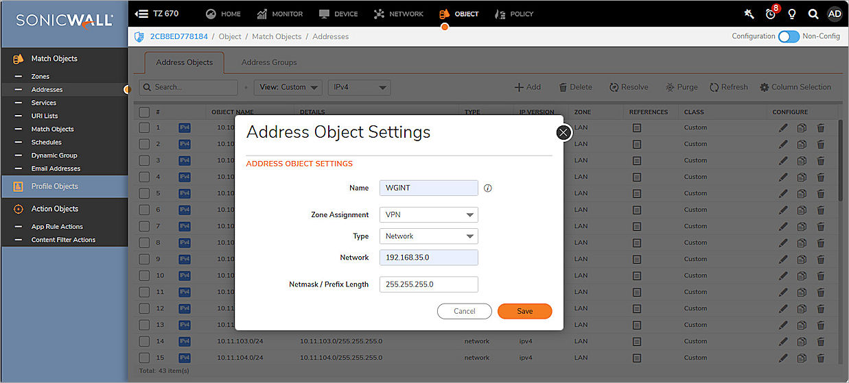
The Address Object Settings dialog box opens. - In the Name text box, type a name for this subnet. In our example, we type WGINT.
- From the Zone Assignment drop-down list, select VPN.
- From the Type drop-down list, select Network.
- In the Network text box, type the IP address of the subnet. In this example, we type 192.168.35.0.
- In the Netmask/Prefix Length text box, type the netmask.
- Click Save.
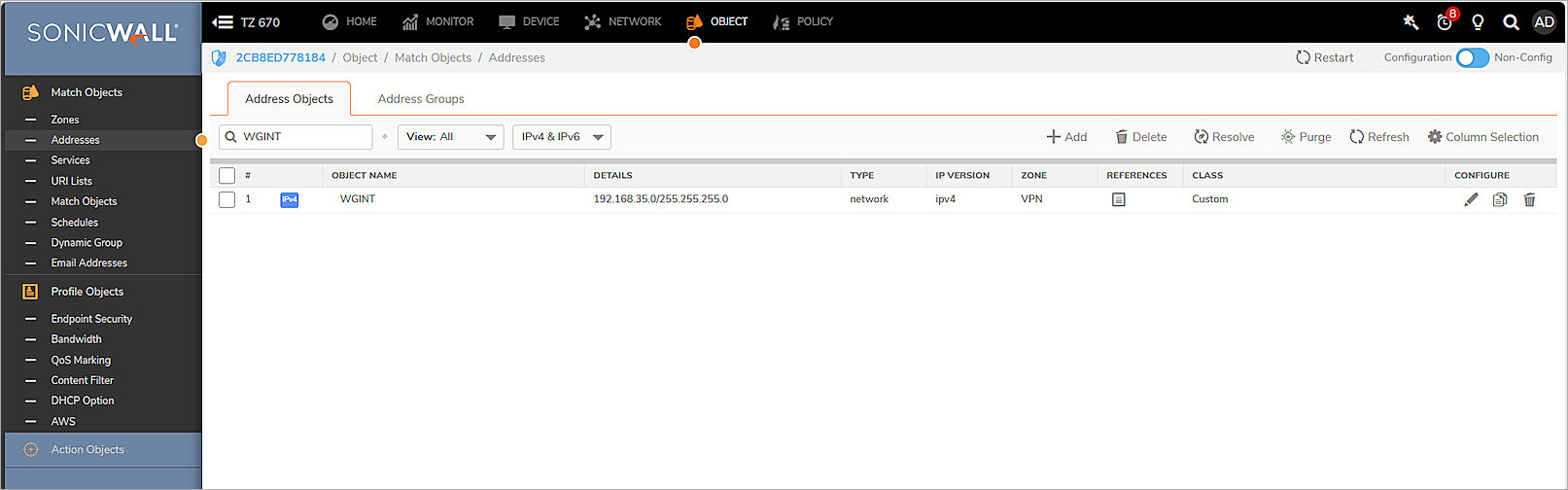
- Click Close.
The VPN tunnel object is created and appears in the list of objects. - Select Network.
- From the navigation menu, select IPSec VPN > Rules and Settings.
- In the Policies section, click Add.
The VPN Policy page opens with General tab selected. - In the Security Policy section:
- From the Policy Type drop-down list, select Site to Site.
- From the Authentication Method drop-down list, select IKE Using Preshared Secret.
- In the Name text box, type a name for this VPN. In our example, we type VPN with WG.
- In the IPsec Primary Gateway Name or Address text box, type the external IP address of your Firebox. In this example, we type 203.0.113.2.
- In the IKE Authentication section:
- Enable Mask Shared Secret.
- In the Shared Secret and Confirm Shared Secret text boxes, type the pre-shared secret key.
- From the Local IKE ID drop-down list, select IPv4 Address. In the adjacent text box, type the SonicWall outgoing public IP address. In this example, we type 198.51.100.2.
- From the Peer IKE ID drop-down list, select IPv4 Address. In the adjacent text box, type the external IP address of your Firebox. In this example, we type 203.0.113.2.
- Keep the default values for all other settings.
- Select the Network tab.
The Network page opens. - In the Local Networks section, select Choose Local Network From List, then from the adjacent drop-down list, select the subnet you have already configured for the SonicWall. In our example, we select X4 Subnet.
- In the Remote Networks section, select Choose Destination Network From List, then from the adjacent drop-down list, select the subnet object you added in Step 5. In our example, we select WGINT.
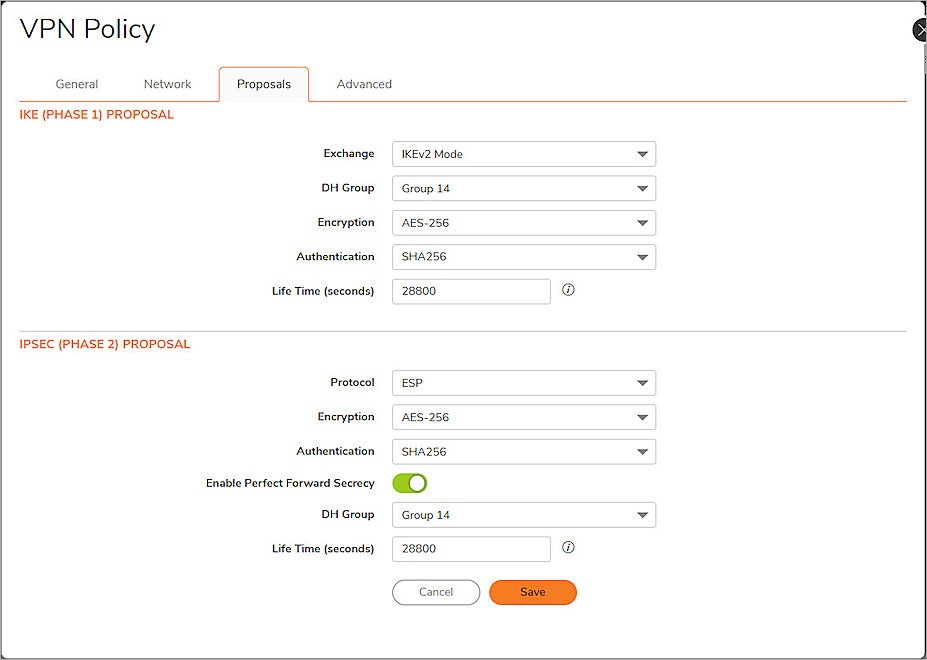
- Select the Proposals tab.
The Proposals page opens. - In the IKE (Phase 1) Proposal section:
- From the Exchange drop-down list, select IKEv2 Mode.
- From the DH Group drop-down list, select Group 14.
- From the Encryption drop-down list, select AES-256.
- From the Authentication drop-down list, select SHA256.
- In the Ipsec (Phase 2) Proposal section:
- From the Protocol drop-down list, select ESP.
- From the Encryption drop-down list, select AES-256.
- From the Authentication drop-down list, select SHA256.
- Enable Enable Perfect Forward Secrecy.
- From the DH Group drop-down list, select Group 14.
- Keep the default values for all other settings.
- Select the Advanced tab.
The Advanced page opens. - Turn on the Enable Keep Alive toggle.
- From the VPN Policy Bound To drop-down list, select the WAN interface for the SonicWall. In this example, we select Interface X1.
- Keep the default values for all other settings.
- Click Save.
- Click Close.
The Advanced VPN Settings page opens. - Keep all default values for all Advanced VPN Settings.
- Click Accept.


Test the Integration
- Log in to SonicWall Firewall Web UI at: https://<IP address of TZ670>.
- Select Network.
- From the navigation mentu, select IPSec VPN > Rules and Settings.
- Select the Active Tunnels tab.
- Verify that the VPN tunnels you configured are active.

- Log in to WatchGuard Cloud.
If you log in with a Service Provider account, you must select a Subscriber account from the Account Manager. - Select the cloud-managed Firebox.
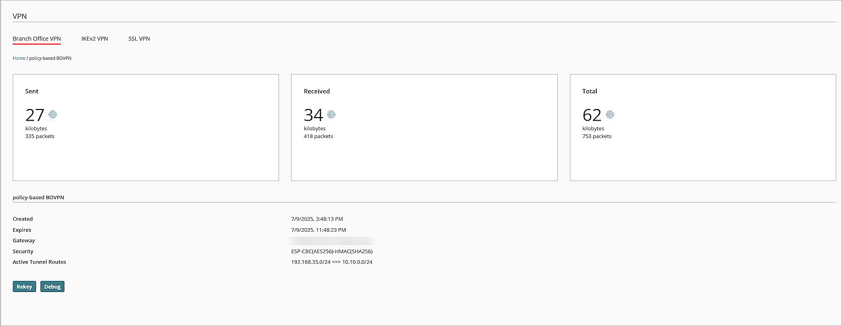
- Select Monitor > Live Status > VPN.
The VPN page opens. - Verify that the VPN tunnels are active.
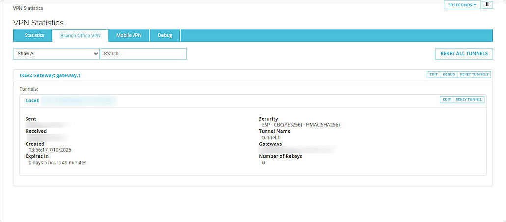
- Log in to Fireware Web UI at: https://<your Firebox IP address>:8080.
- Select System Status > VPN Statistics.
The VPN Statistics page opens. - Select the Branch Office VPN tab.
The Branch Office VPN page opens. - In the Tunnels section, verify that the VPN tunnels are active.