This integration guide describes how to configure a policy-based Branch Office VPN (BOVPN) between a WatchGuard Firebox and a pfSense firewall.
Contents
Integration Summary
The hardware and software used in this guide include:
- WatchGuard Firebox with Fireware v12.11.2 (B713726)
- pfSense device with v2.8.0-BETA (amd64)
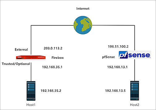
Integration Topology
This diagram outlines the topology used in this integration.
Configure the Firebox
You can configure your Firebox for a policy-based BOVPN from WatchGuard Cloud for a cloud-managed Firebox or Fireware Web UI for a locally-managed Firebox.
- Log in to WatchGuard Cloud with your WatchGuard Cloud operator account credentials.
If you log in with a Service Provider account, you must select a Subscriber account from the Account Manager. - From the top navigation menu, select Configure > VPNs.
- Click Add BOVPN.
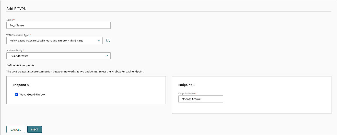
The Add BOVPN page opens. - In the Name text box, type a descriptive name.
- For VPN Connection Type, select Policy-Based IPSec to Locally-Managed Firebox / Third-Party.
- From the Address Family drop-down list, select IPv4 Addresses.
- In the Endpoint A section, select your cloud-managed Firebox.
- In the Endpoint B section, in the Endpoint Name text box, type a name to identify the remote VPN endpoint. In our example, we type pfSense firewall.
- Click Next.
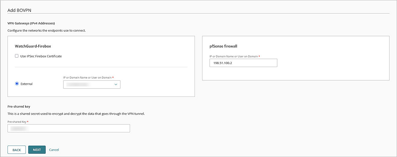
- For your cloud-managed Firebox:
- Select External.
- In the IP or Domain Name or User on Domain text box, select an IP address, domain name, or user on domain that resolves to the Firebox external network IP address.
- For the remote VPN endpoint, in the IP or Domain Name or User on Domain text box, type the IP address of your pfSense firewall WAN connection.
- In the Pre-Shared Key text box, type a pre-shared key. This pre-shared key matches the pre-shared key when you configure the pfSense IPSec VPN Phase 1 settings.
- Click Next.
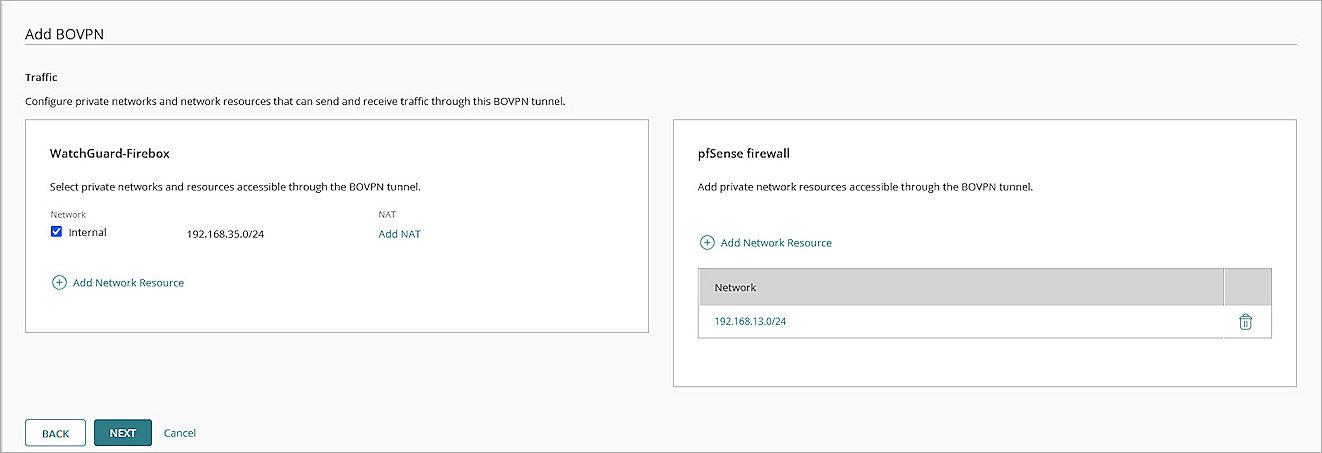
- In the cloud-managed Firebox section, select the internal networks that you want to be accessible through the VPN tunnel.
- In the pfSense endpoint section, click Add Network Resource.
- In the Network Resource text box, type the private network protected by the pfSense firewall. For our example, we type 192.168.13.0/24.
- Click Add.
- For all other settings, keep the default values.
- Click Next.
The Tunnel Routes page opens.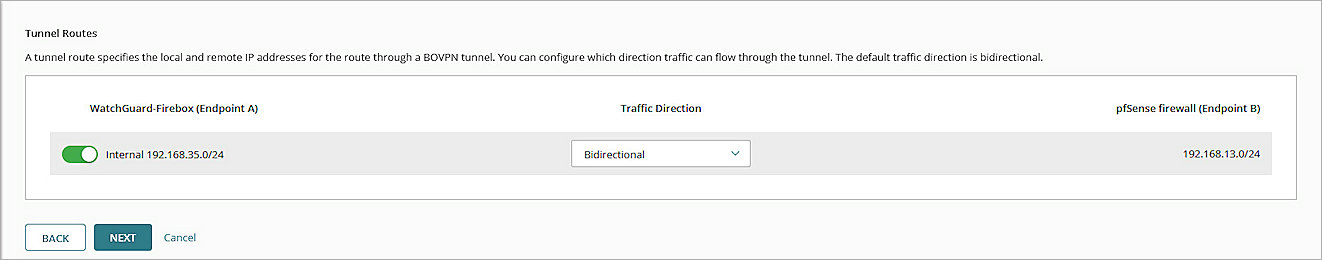
- Click Next.
- In the Phase 1 Settings section, from the Authentication drop-down list, select SHA2-256.
- From the Encryption drop-down list, select AES-CBC (256-bit).
- In the SA Life text box, type 24.
- From the Diffie-Hellman Group drop-down list, select Diffie-Hellman Group14.
- In the Phase 2 Settings section, from the Authentication drop-down list, select SHA2-256.
- From the Encryption drop-down list, select AES-CBC (256-bit).
- Select the Use Perfect Forward Secrecy (PFS) check box.
- From the PFS Group drop-down list, select Diffie-Hellman Group14.
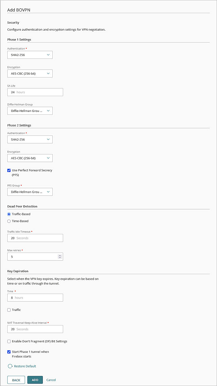
- Keep the default values for all other settings.
- Click Add.
- (Optional) To open the VPN Configuration Summary page for the cloud-managed Firebox, click View Guide.
- Click Finish.
WatchGuard Cloud creates and deploys a configuration update for the cloud-managed Firebox.
- Log in to Fireware Web UI at: https://<your Firebox IP address>:8080.
- Select VPN > Branch Office VPN.
The Branch Office VPN configuration page opens. - In the Gateways section, click Add.
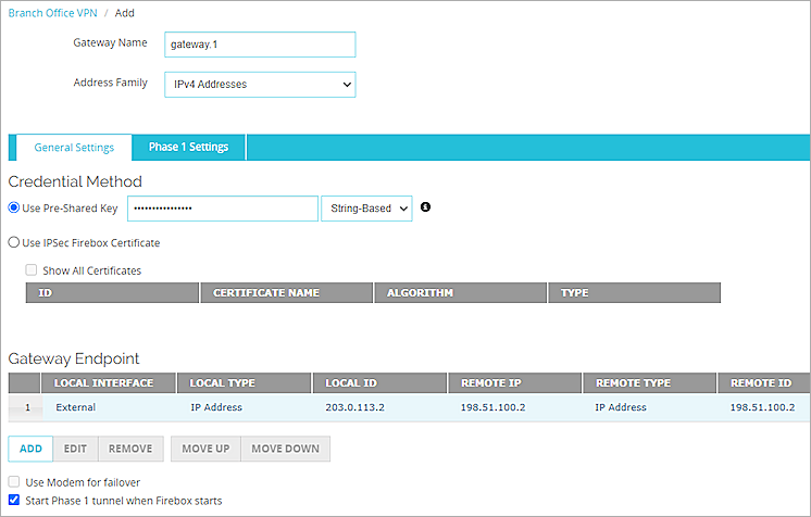
The Add Branch Office VPN page opens. - In the Gateway Name text box, type a name to identify this BOVPN gateway.
- From the Address Family drop-down list, select IPv4 Addresses.
- In the Credential Method section:
- Select Use Pre-Shared Key.
- In the Use Pre-Shared Key text box, type the pre-shared key.
- From the drop-down list, select String-Based.
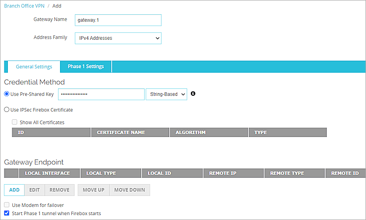
- Select Use Pre-Shared Key.
- In the Gateway Endpoint section, click Add.
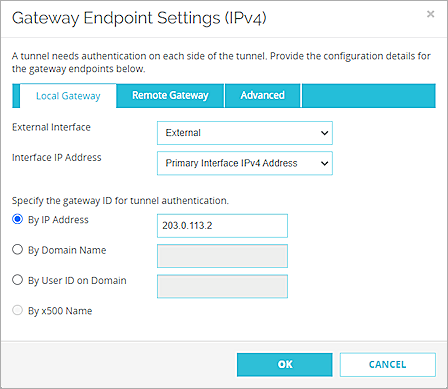
The Gateway Endpoint Settings dialog box opens. - From the External Interface drop-down list, select the interface that has the external (public) IP address of the Firebox.
- From the Interface IP Address drop-down list, select Primary Interface IPv4 Address.
The Primary Interface IP Address is the primary IP address you configured on the selected external interface. - For Specify the Gateway ID for Tunnel Authentication, select By IP Address.
- In the adjacent text box, type the primary IP address of the Firebox external interface.
- Select the Remote Gateway tab.
The Remote Gateway page opens. - For Specify the Remote Gateway IP Address for a Tunnel, select Static IP Address.
- In the adjacent text box, type the IP address of your pfSense WAN connection.
- For Specify the Remote Gateway ID for Tunnel Authentication, select By IP Address.
- In the adjacent text box, type the IP address of your pfSense WAN connection.
- Keep the default values for all other settings.
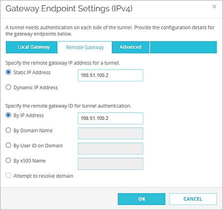
- Click OK.
The gateway you added appears in the Gateway Endpoint section. - In the Gateway Endpoint section, select the Start Phase 1 Tunnel When Firebox Starts check box.
- Select the Phase 1 Settings tab.
The Phase 1 Settings page opens. - From the Version drop-down list, select IKEv2.
- Keep the default values for all of the Phase 1 settings.
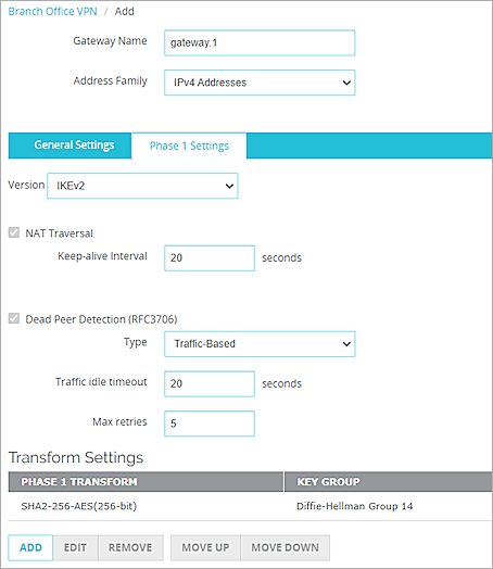
- Click Save.
The gateway you added appears on the Branch Office VPN page. - In the Tunnels section, click Add.
The tunnel settings page opens.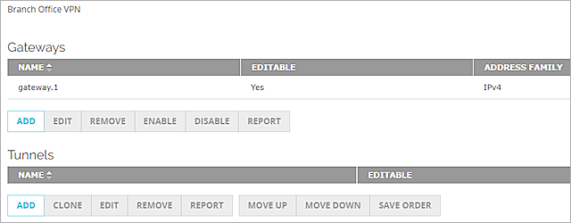
- In the Name text box, type a name to identify this tunnel.
- From the Gateway drop-down list, select the gateway you just created.
- In the Addresses section, click Add.
The Tunnel Route Settings dialog box opens. - In the Local IP section:
- From the Choose Type drop-down list, select Network IPv4.
- In the Network IP text box, type the local IP address. This IP address is the internal network that the Firebox protects.
- In the Remote IP section:
- From the Choose Type drop-down list, select Network IPv4.
- In the Network IP text box, type the remote IP address. This IP address is the internal network that the pfSense firewall protects.
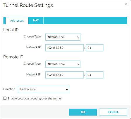
- Click OK.
- Keep the default values for all Phase 2 settings.
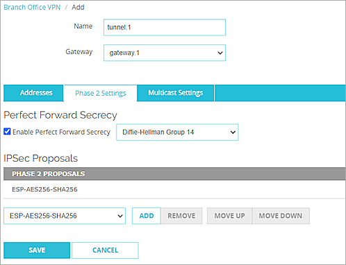
- Click Save.
Configure pfSense
This section describes how to configure the pfSense settings.
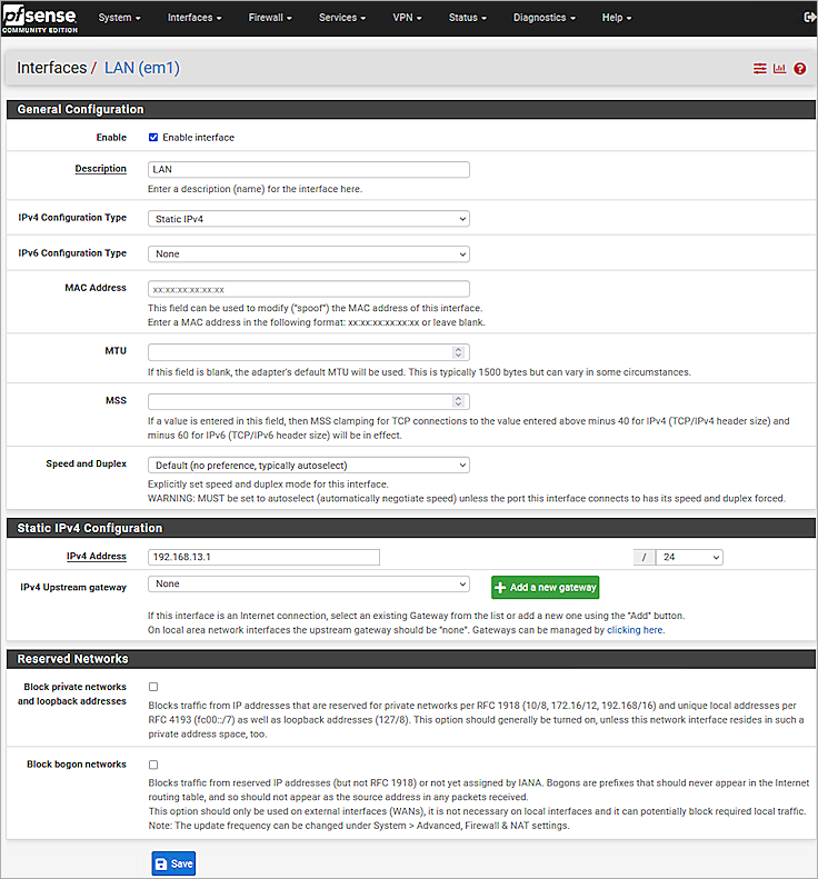
Configure Basic Settings
- Log in to the pfSense Web UI at: https://<IP address of the pfSense>
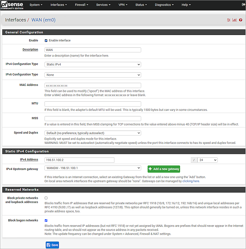
The default IP address of the interface is: https://192.168.1.1 - Configure the pfSense interfaces. For information about how to configure interfaces, go to the pfSense documentation.
Configure the pfSense IPSec VPN Phase 1 and 2 Settings
- Log in to the pfSense Web UI at: https://<IP address of the pfSense device>
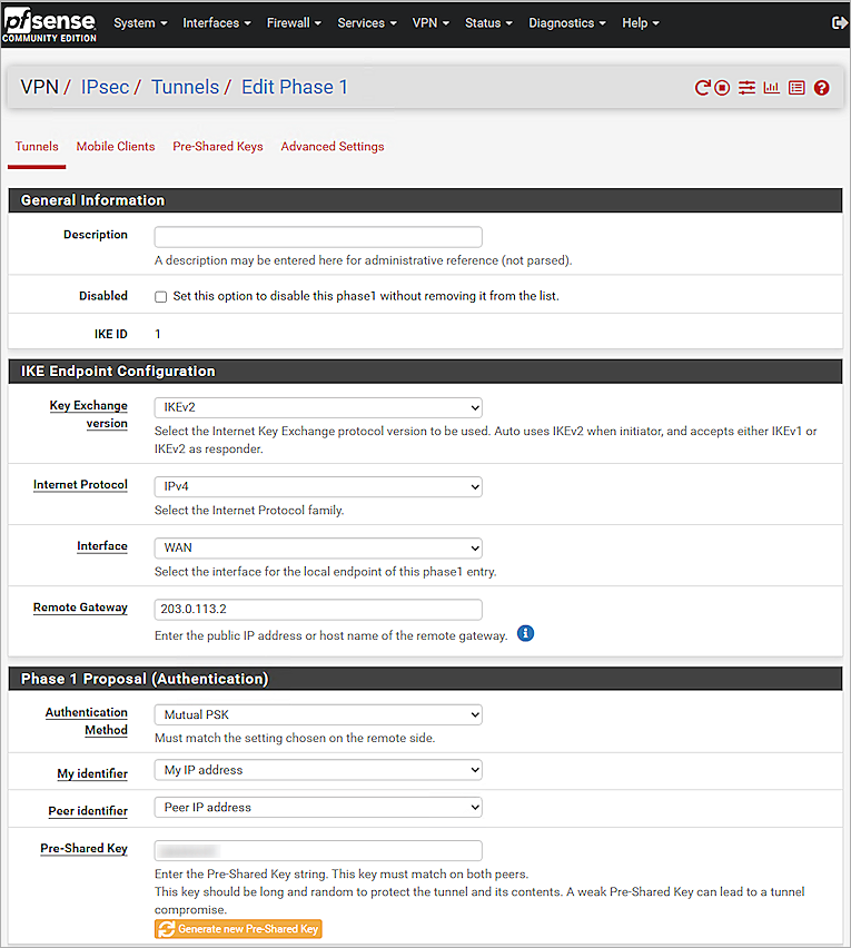
- Select VPN > IPsec > Tunnels.
- Click + Add P1.
- In the IKE Endpoint Configuration section, from the Key Exchange Version drop-down list, select IKEv2.
- From the Internet Protocol drop-down list, select IPv4.
- From the Interface drop-down list, select WAN.
- In the Remote Gateway text box, type the external IP address of the Firebox.
- In the Phase 1 Proposal (Authentication) section, from the Authentication Method drop-down list, select Mutual PSK.
- From the My Identifier drop-down list, select My IP Address.
- From the Peer Identifier drop-down list, select Peer IP address.
- In the Pre-Shared Key text box, type the pre-shared key.
- In the Phase 1 Proposal (Encryption Algorithm) section, from the Algorithm drop-down list, select AES.
- From the Key Length drop-down list, select 256 bits.
- From the Hash drop-down list, select SHA256.
- From the DH Group drop-down list, select 14 (2048 bit).
- In the Life Time text box, type 28800.
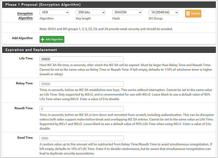
- Keep the default values for all other settings.
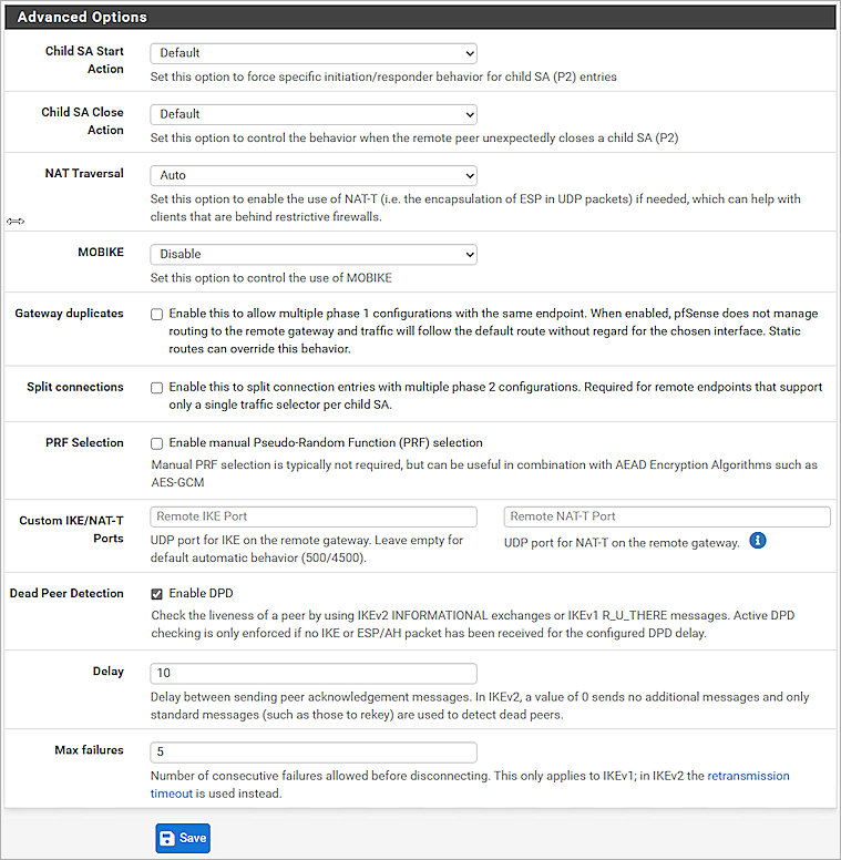
- Click Save.
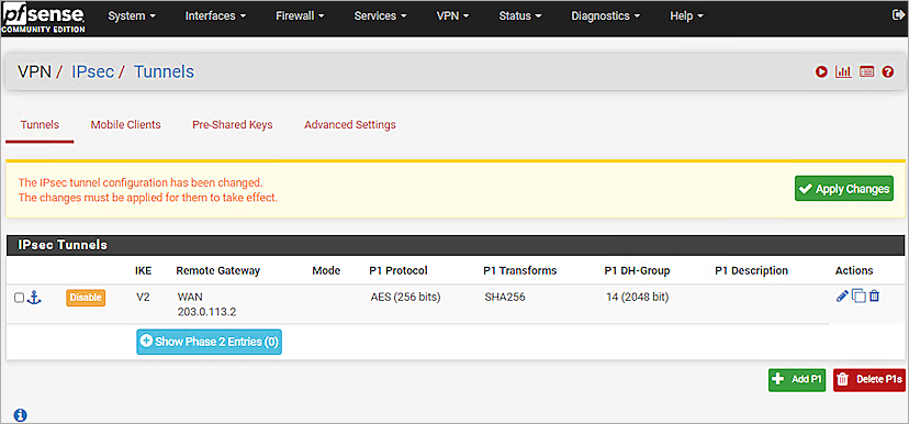
- Click Show Phase 2 Entries.
- Click + Add P2.
- In the General Information section, from the Mode drop-down list, select Tunnel IPv4.
- For Local Network, from the Type drop-down list, select Network.
- In the Address text box, type the local network IP address.
- For Remote Network, from the Type drop-down list, select Network.
- In the Address text box, type the remote network IP address.
- In the Phase 2 Proposal (SA/Key Exchange) section, from the Protocol drop-down list, select ESP.
- For Encryption Algorithms, select AES. In the adjacent drop-down list, select 256 bits. Do not select the AES128-GCM check box.
- For Hash Algorithms, select the SHA256 check box.
- From the PFS Key Group drop-down list, select 14 (2048 bit).
- In the Life Time text box, type 3600.
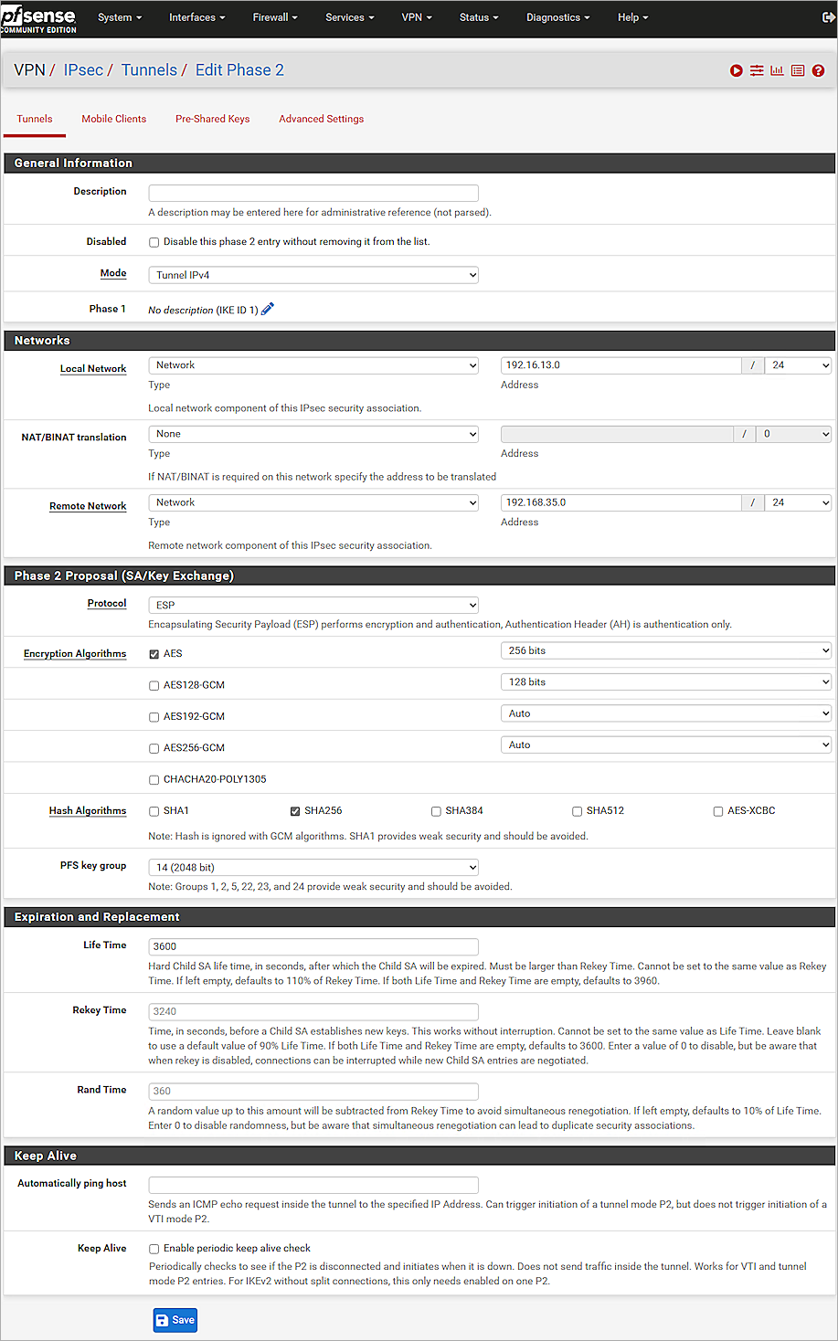
- Click Save.
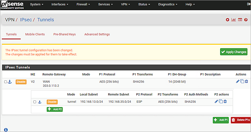
- Click Apply Changes.
Configure Rule Settings
- Log in to the pfSense Web UI at: https://<IP address of the pfSense device>
- Select Firewall > Rules > IPsec.
- Click Add.
- From the Action drop-down list, select Pass.
- From the Protocol drop-down list, select Any.
- From the Source drop-down list, select Network.
- In the Source Address text box, type the remote network IP address.
- From the Destination drop-down list, select Network.
- In the Destination Address text box, type the local network IP address.
- Keep the default values for all other settings.
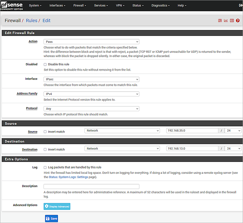
- Click Save.
- (Optional) Repeat Steps 2-10 to create another rule.
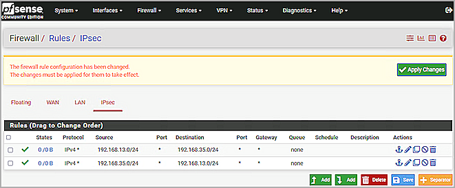
- Click Apply Changes.
Test the Integration
- Log in to WatchGuard Cloud.
- From the navigation menu, select Monitor > Devices.
If you log in as a Service Provider, you must select a Subscriber account from the Account Manager. - Select the cloud-managed Firebox.
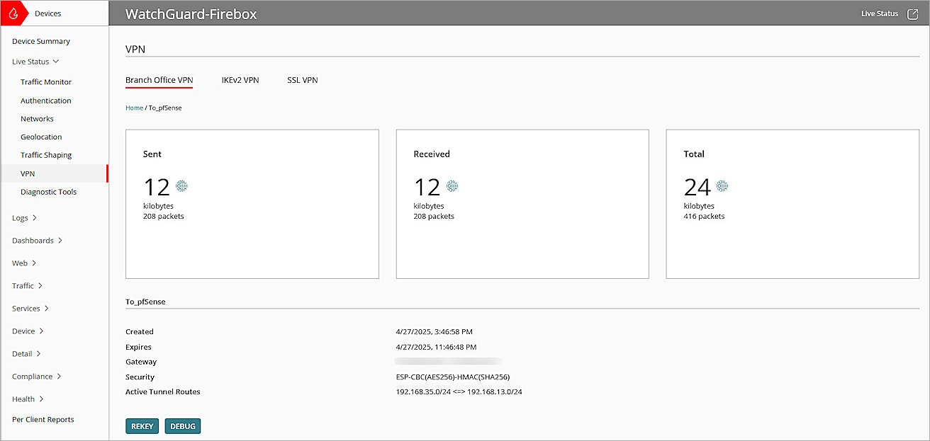
- Select Monitor > Live Status > VPN.
The VPN page opens. - Select the Branch Office VPN tab.
- Click the BOVPN you configured.
- To make sure that Host 1 (behind the Firebox) and Host 2 (behind the pfSense firewall) can communicate with each other, use the Ping utility.
- Log in to Fireware Web UI at: https://<your Firebox IP address>:8080.
- Select System Status > VPN Statistics.
The VPN Statistics page opens. - Select the Branch Office VPN tab.
The Branch Office VPN page opens. - Verify that the VPN is established.
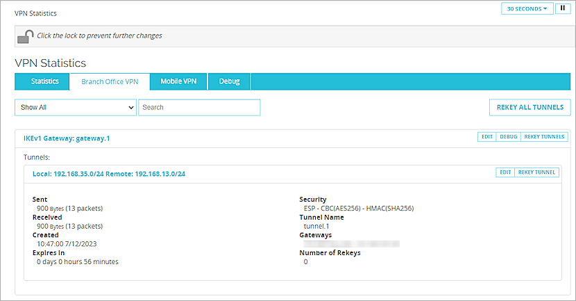
- Verify that Host 1 (behind the Firebox) and Host 2 (behind the pfSense firewall) can successfully ping each other.
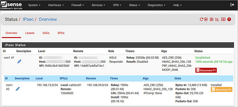
- Log in to the pfSense Web UI.
- Select Status > IPSec > Overview.
- Verify that the IPSec tunnel is established and the child SA status is connected.