This integration guide describes how to configure a policy-based Branch Office VPN (BOVPN) between a WatchGuard Firebox and a Palo Alto PA-220 firewall.
Contents
Integration Summary
The hardware and software used in this guide include:
- Firebox with Fireware v12.11.2
- Palo Alto PA-220 v10.2.4
Integration Topology
This diagram shows the topology for a policy-based BOVPN connection between a Firebox and a Palo Alto PA-220 firewall.
Before You Begin
Before you begin these procedures, make sure that:
- If you want to use a cloud-managed Firebox, you have a WatchGuard Cloud account and have added the Firebox to WatchGuard Cloud as a cloud-managed device. You also have configured an external network with the external (public) IP address of the Firebox and at least one internal network on the Firebox.
- If you want to use a locally-managed Firebox, you have configured an external interface with the external (public) IP address of the Firebox and at least one internal interface on the Firebox.
- You have configured the Palo Alto PA-220 with Layer 3 interfaces, Trust and Untrust security zones, and a static route to the Internet. For more information go to the Palo Alto documentation.
Configure the Firebox
You can configure your Firebox for a policy-based BOVPN from WatchGuard Cloud for a cloud-managed Firebox or Fireware Web UI for a locally-managed Firebox.
- Log in to WatchGuard Cloud.
If you log in with a Service Provider account, you must select a Subscriber account from the Account Manager. - From the navigation menu, select Configure > VPNs.
The BOVPN page opens. - Click Add BOVPN.
The Add BOVPN page opens. - In the Name text box, type a descriptive name for the BOVPN. In this example, we type To_Palo-Alto.
- From the VPN Connection Type drop-down list, select Policy-Based IPSec to Locally-Managed Firebox / Third-Party.
- From the Address Family drop-down list, select IPv4 Addresses.
- In the Endpoint A section, select your cloud-managed Firebox.
- In the Endpoint B section, in the Endpoint Name text box, type a name to identify the remote VPN endpoint. In our example, we type Palo Alto.
- Click Next.
The VPN Gateways settings page opens. - For your cloud-managed Firebox, select External.
- In the IP or Domain Name or User on Domain text box, select an IP address, domain name, or user on domain that resolves to the Firebox external network IP address.
- For the remote VPN endpoint, in the IP or Domain Name or User on Domain text box, type the IP address of your Palo Alto WAN connection. In this example, we type 198.51.100.2.
- To encrypt and decrypt the data that goes through the VPN tunnel, in the Pre-Shared Key text box, type a shared key. This pre-shared key matches the pre-shared key you will configure for the IKE Gateway on the Palo Alto firewall.
- Click Next.
The Traffic settings page opens. - For your cloud-managed Firebox, select the internal networks that you want to be accessible through the VPN tunnel.
- For the Palo Alto VPN endpoint, click Add Network Resource.
- In the Network Resource text box, type the private network protected by the Palo Alto firewall. In our example, we type 192.168.13.0/24.
- Click Add.
- Keep the default values for all other settings.
- Click Next.
The Tunnel Routes page opens. - Keep the default values for all settings.
- Click Next.
The security settings page opens. - In the Phase 1 Settings section:
- From the Authentication drop-down list, select SHA2-256.
- From the Encryption drop-down list, select AES-CBC (256-bit).
- In the SA Life text box, type 8.
- From the Diffie-Hellman Group drop-down list, select Diffie-Hellman Group14.
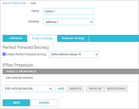
- In the Phase 2 Settings section:
- From the Authentication drop-down list, select SHA2-256.
- From the Encryption drop-down list, select AES-CBC (256-bit).
- Select the Use Perfect Forward Secrecy (PFS) check box.
- From the PFS Group drop-down list, select Diffie-Hellman Group14.
- Keep all default values for all other settings.
- Click Add.
- (Optional) To open the VPN Configuration Summary page for the cloud-managed Firebox, click View Guide.
To establish the VPN connection, configure the required settings on the Palo Alto firewall. For more information, go to Configure the Palo Alto Firewall.
- Click Finish.
WatchGuard Cloud creates and deploys a configuration update for the cloud-managed Firebox.


- Log in to Fireware Web UI.
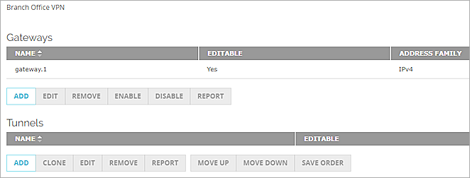
- Select VPN > Branch Office VPN.
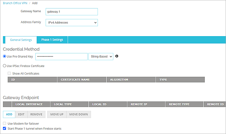
The Branch Office VPN configuration page opens. - In the Gateways section, click Add.
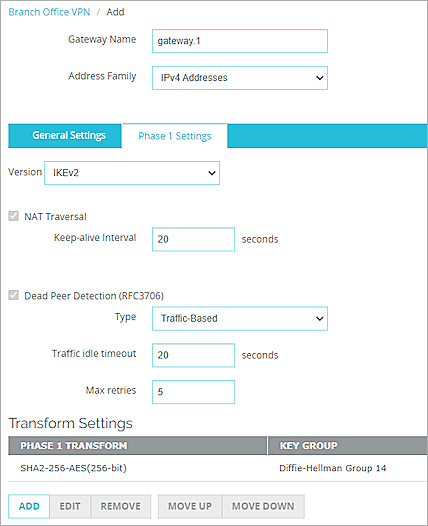
The Add page opens. - In the Gateway Name text box, type a name to identify this BOVPN gateway. In this example, we type gateway.1.
- From the Address Family drop-down list, select IPv4 Addresses.
- In the Credential Method section:
- Select Use Pre-Shared Key.
- In the Use Pre-Shared Key text box, type the pre-shared key. This pre-shared key matches the pre-shared key you will configure for the IKE Gateway on the Palo Alto firewall.
- From the drop-down list, select String-Based.
- Select Use Pre-Shared Key.
- In the Gateway Endpoint section, click Add.
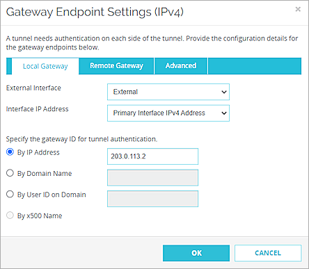
The Gateway Endpoint Settings dialog box opens. - From the External Interface drop-down list, select the interface that has the external (public) IP address of the Firebox.
- From the Interface IP Address drop-down list, select Primary Interface IPv4 Address.
The Primary Interface IP Address is the primary IP address you configured on the selected external interface. - For Specify the Gateway ID for Tunnel Authentication, select By IP Address.
- In the adjacent text box, type the primary IP address of the Firebox external interface. In this example, we type 203.0.113.2.
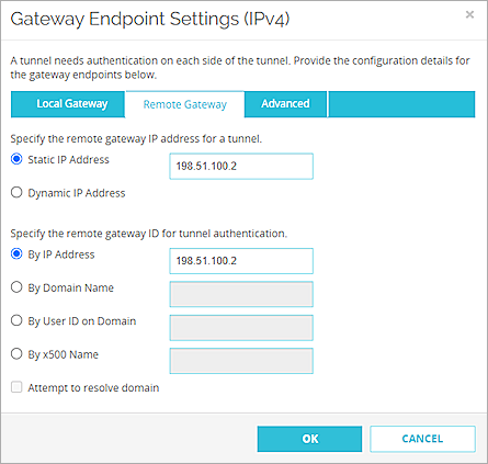
- Select the Remote Gateway tab.
The Remote Gateway page opens. - For Specify the Remote Gateway IP Address for a Tunnel, select Static IP Address.
- In the adjacent text box, type the IP address of your Palo Alto WAN connection. In this example, we type 198.51.100.2.
- For Specify the Remote Gateway ID for Tunnel Authentication, select By IP Address.
- In the adjacent text box, type the IP address of your Palo Alto WAN connection. In this example, we type 198.51.100.2.
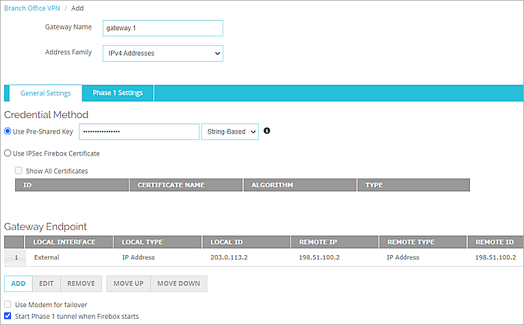
- Click OK.
The gateway endpoint you added appears in the Gateway Endpoint section. - In the Gateway Endpoint section, select the Start Phase 1 Tunnel When Firebox Starts check box.
- Select the Phase 1 Settings tab.
The Phase 1 Settings page opens. - From the Version drop-down list, select IKEv2.
- Keep the default values for all other Phase 1 settings.
- Click Save.
The gateway you added appears on the Branch Office VPN page. - In the Tunnels section, click Add.
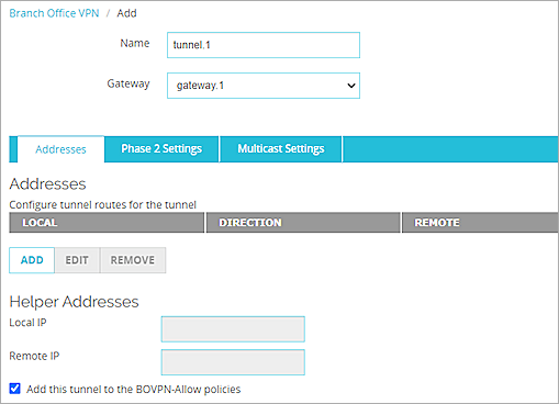
The tunnel settings page opens. - In the Name text box, type a name to identify the tunnel. In this example, we type tunnel.1.
- From the Gateway drop-down list, select the gateway you just configured. In this example, we select gateway.1.
- From the Addresses section, click Add.
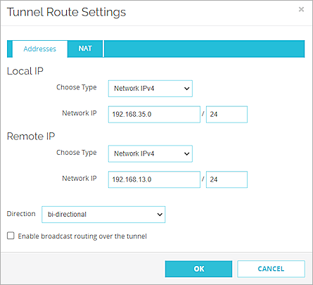
The Tunnel Route Settings dialog box opens. - In the Local IP section:
- From the Choose Type drop-down list, select Network IPv4.
- In the Network IP text box, type the local IP address. This IP address is the internal network that the VPN protects. In this example, we type 192.168.35.0.
- In the Remote IP section:
- From the Choose Type drop-down list, select Network IPv4.
- In the Network IP text box, type the remote IP address. This IP address is the internal network that the VPN protects. In this example, we type 192.168.13.0.
- Click OK.
- Keep the default values for all Phase 2 settings.
- Click Save.
The settings you configured are saved.
Configure the Palo Alto Firewall
To configure the Palo Alto firewall, complete these steps:
- Configure a Tunnel Interface
- Configure a Static Route
- Configure the IKE Crypto Profile
- Configure the IPSec Crypto Profile
- Configure the IKE Gateway
- Configure the IPSec Tunnel
- Configure the Security Policy
Configure a Tunnel Interface
To configure a tunnel interface on the Palo Alto firewall:
- Log in to the Palo Alto Web UI at: https://<IP address of the Palo Alto device>.
The default IP address is https://192.168.1.1. - Select Network > Interfaces > Tunnel.
The Tunnel page opens. - Click Add.
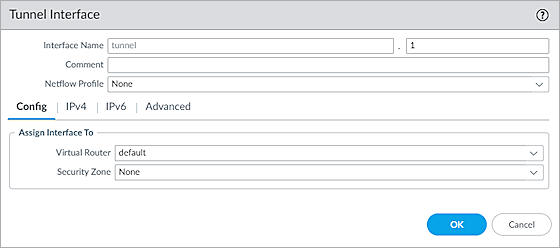
The Tunnel Interface dialog box opens. - In the Interface Name text box, type a numeric suffix. In our example, we type 1.
- Select the Config tab.
- From the Virtual Router drop-down list, select Default.
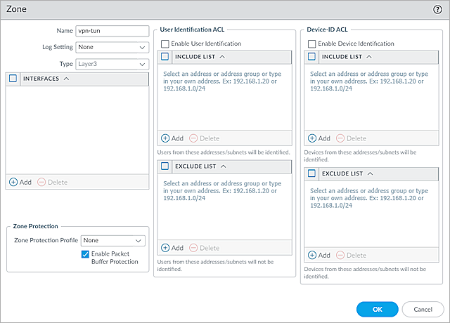
- From the Security Zone drop-down list, select New Zone.
The Zone dialog box opens. - In the Name text box, type a name for the zone. In this example, we type vpn-tun.
- To save the zone, click OK.
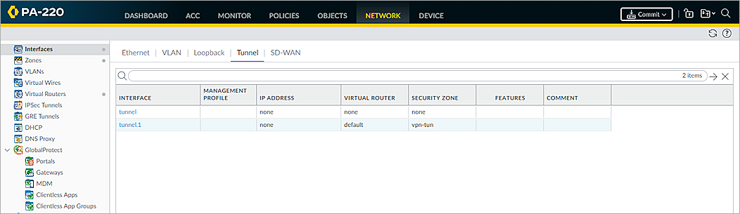
- To save the tunnel interface, click OK.
The tunnel interface is added and appears on the Tunnel page.
Configure a Static Route
To configure a static route on the Palo Alto firewall, from the Palo Alto Web UI:
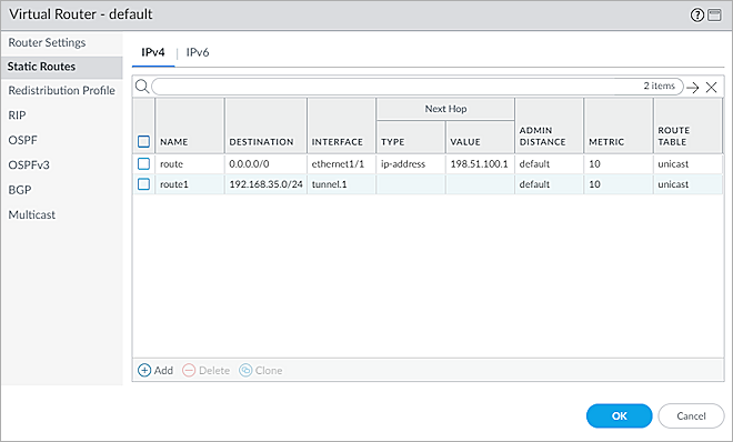
- Select Network > Virtual Routers.
The list of existing virtual routers opens. - In the list of virtual routers, click the Default virtual router.
- Click Static Routes.
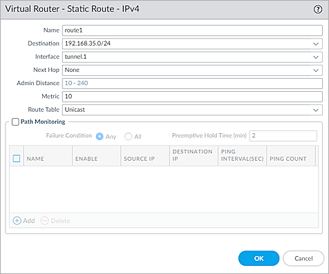
- Click Add.
The static route settings open. - In the Name text box, type a name for the route. In this example, we type route1.
- In the Destination text box, type the destination address. In this example, we type 192.168.35.0/24.
- From the Interface drop-down list, select tunnel.1.
- From the Next Hop drop-down list, select None.
- To save the static route settings, click OK.
- To save the virtual router settings, click OK.
The updates to the Default virtual router configuration are saved.

Configure the IKE Crypto Profile
To configure the IKE crypto profile on the Palo Alto firewall, from the Palo Alto Web UI:
- Select Network > Network Profiles > IKE Crypto.
The list of existing IKE crypto profiles opens. - Click Add.
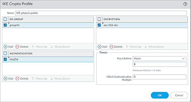
The IKE Crypto Profile dialog box opens. - In the Name text box, type a name for the profile. In this example, we type IKE-phase1-profile.
- In the DH Group section, click Add, then select the group14 check box.
- In the Encryption section, click Add, then select the aes-256-cbc check box.
- In the Authentication section, click Add, then select the sha256 check box.
- Keep the default values for all other settings.
- Click OK.
The profile is added to the list of IKE crypto profiles.
Configure the IPSec Crypto Profile
To configure the IPSec crypto profile on the Palo Alto firewall, from the Palo Alto Web UI:
- Select Network > Network Profiles > IPSec Crypto.
The list of existing IPSec crypto profiles opens. - Click Add.
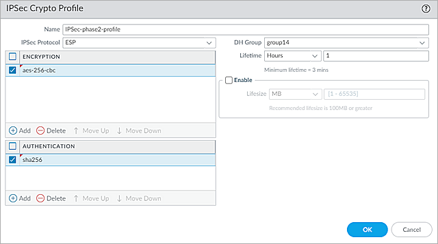
The IPSec Crypto Profile dialog box opens. - In the Name text box, type a name for the IPSec Crypto profile. In this example, we type IPSec-phase2-profile.
- From the IPSec Protocol drop-down list, select ESP.
- In the Encryption section, click Add, then select the aes-256-cbc check box.
- From the DH Group drop-down list, select group14.
- In the Authentication section, click Add, then select the sha256 check box.
- Keep the default values for all other settings.
- Click OK.
The profile is added to the list of IPSec crypto profiles.
Configure the IKE Gateway
To configure the IKE gateway on the Palo Alto firewall, from the Palo Alto Web UI:
- Select Network > Network Profiles > IKE Gateways.
The list of existing IKE gateways opens. - Click Add.
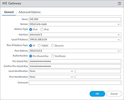
The IKE Gateway dialog box opens with the General tab selected by default. - In the Name text box, type a name for the IKE gateway. In this example, we type IKE-GW.
- From the Version drop-down list, select IKEv2 Only Mode.
- For Address Type, select IPv4.
- From the Interface drop-down list, select Ethernet1/1.
- From the Local IP Address drop-down list, select the IP address for the Palo Alto WAN connection. In this example, we select 198.51.100.2/24.
- For Peer IP Address Type, select IP.
- In the Peer Address text box, type the primary IP address of the external Firebox interface. In this example, we type 203.0.113.2.
- For Authentication, select Pre-Shared Key.
- In the Pre-Shared Key text box, type the same pre-shared key you configured on the Firebox.
- In the Confirm Pre-Shared Key text box, type the pre-shared key again.
- From the Local Identification drop-down list, select None.
- From the Peer Identification drop-down list, select None.
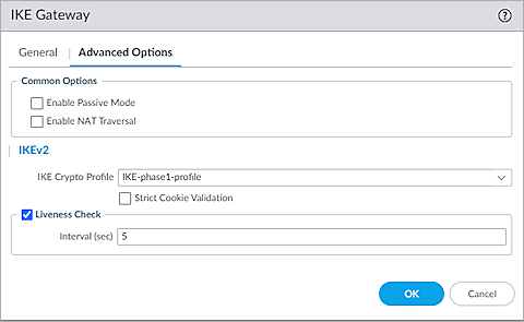
- Select the Advanced Options tab.
The Advanced Options page opens. - In the IKEv2 section, from the IKE Crypto Profile drop-down list, select the IKE crypto profile you created in the Configure the IKE Crypto Profile section. In this example, we select IKE-phase1-profile.
- Click OK.
The gateway is added to the list of IKE gateways.
Configure the IPSec Tunnel
To configure the IPSec tunnel on the Palo Alto firewall, from the Palo Alto Web UI:
- Select Network > IPSec Tunnels.
The list of existing IPSec tunnels opens. - Click Add.
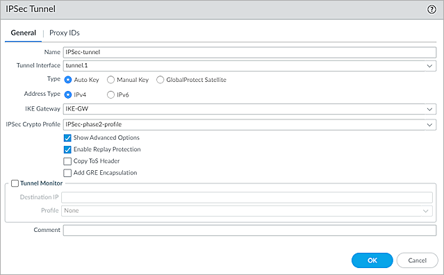
The IPSec Tunnel dialog box opens with the General tab selected by default. - In the Name text box, type a name for the tunnel. In this example, we type IPSec-tunnel.
- From the Tunnel Interface drop-down list, select the tunnel interface you created in the Configure a Tunnel Interface section. In this example, we type tunnel.1.
- For Type, select Auto Key.
- For Address Type, select IPv4.
- From the IKE Gateway drop-down list, select the gateway you created in the Configure the IKE Gateway section. In this example, we select IKE-GW.
- From the IPSec Crypto Profile drop-down list, select the IPSec crypto profile you created in the Configure the IPSec Crypto Profile section. In this example, we select IPSec-phase2-profile.
- Select the Show Advanced Options check box.
- Select the Enable Replay Protection check box.
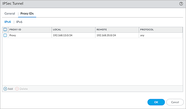
- Select the Proxy IDs tab.
- Click IPv4.
- Click Add.
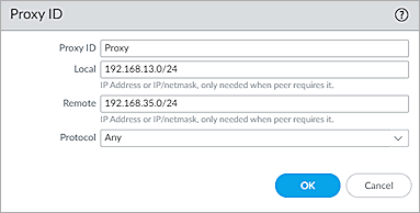
The Proxy ID dialog box opens. - In the Proxy ID text box, type a Proxy ID name. In this example, we type Proxy.
- In the Local text box, type the IP address or subnet for the local VPN gateway. In this example, we type 192.168.13.0/24.
- In the Remote text box, type the IP address or subnet for the remote VPN gateway. In this example, we type 192.168.35.0/24.
- From the Protocol drop-down list, select Any.
- Click OK.
- Click OK.
The tunnel is added to the list of IPSec tunnels.
Configure the Security Policy
To configure a security policy on the Palo Alto firewall, from the Palo Alto Web UI:
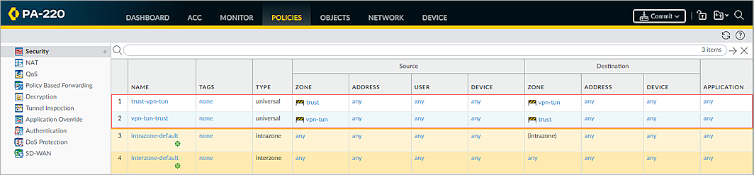
- Select Policies > Security.
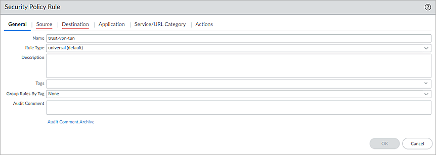
The list of existing security policies opens. - Click Add.
The Security Policy Rule dialog box opens with the General tab selected by default. - In the Name text box, type a name for the policy. In this example, we type trust-vpn-tun.
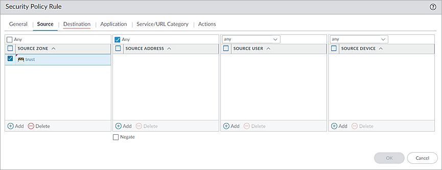
- Select the Source tab.
The Source page opens. - In the Source Zone section, click Add, then select Trust.
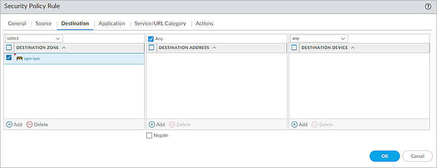
- Select the Destination tab.
The Destination page opens. - In the Destination Zone section, click Add, then select the security zone you created in the Configure a Tunnel Interface section. In this example, we select vpn-tun.
- Keep the default values for all other settings.
- Click OK.
- To create another security policy, repeat Steps 1-9.
- Click Commit.
The firewall can take several minutes to save your change. - Click Close.
Test the Integration
- Log in to WatchGuard Cloud.
If you log in with a Service Provider account, you must select a Subscriber account from the Account Manager. - Select the cloud-managed Firebox.
- Select Monitor > Live Status > VPN.
The VPN page opens with the Branch Office VPN tab selected by default. - Verify that Host 1 (behind the Firebox) and Host 2 (behind the Palo Alto firewall) can ping each other.

- Log in to Fireware Web UI.
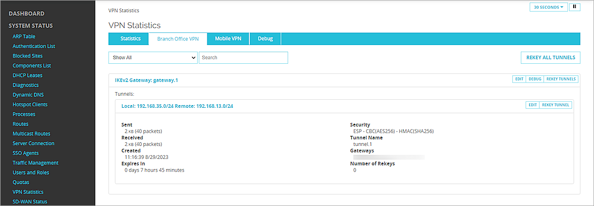
- Select System Status > VPN Statistics.
The VPN Statistics page opens. - Select the Branch Office VPN tab.
The Branch Office VPN page opens. - Verify that the VPN is established.
- Verify that Host 1 (behind the Firebox) and Host 2 (behind the Palo Alto firewall) can ping each other.
- Log in to Palo Alto Firewall.
- Select Network > IPSec Tunnels.
- Make sure all the status columns are up and the status icons are green.
