Deployment Overview
WatchGuard provides integration instructions to help our customers configure WatchGuard products to work with products created by other organizations. If you need more information or technical support about how to configure a third-party product, see the documentation and support resources for that product.
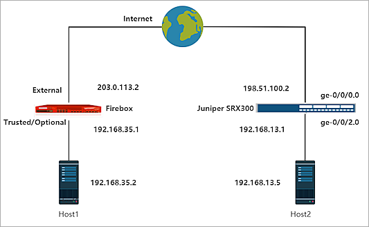
This integration guide describes how to configure a Branch Office VPN (BOVPN) tunnel between a WatchGuard Firebox and a Juniper® SRX300.
Integration Summary
The hardware and software used in this guide include:
- WatchGuard Firebox with Fireware v12.7
- Juniper SRX300 v19.4R3-S1.3
Integration Topology
This diagram shows the topology for a BOVPN connection between a Firebox and a Juniper SRX300.
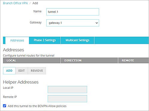
Configure the Firebox
On the Firebox, configure a Branch Office VPN (BOVPN) connection:
- Log in to Fireware Web UI.
- Select VPN > Branch Office VPN.
The Branch Office VPN configuration page opens. - In the Gateways section, click Add.
- In the Gateway Name text box, type a name to identify this BOVPN gateway.
- From the Address Family drop-down list, select IPv4 Addresses.
- In the Credential Method section, select Use Pre-Shared Key.
- In the adjacent text box, type the pre-shared key.
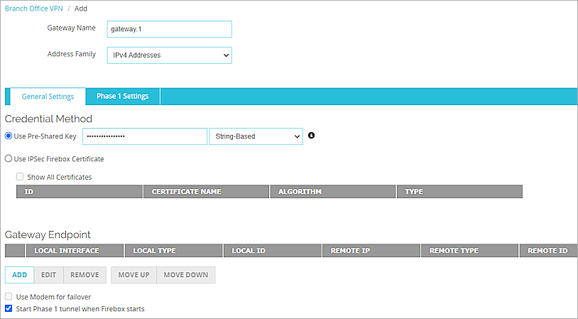
- In the Gateway Endpoint section, click Add.
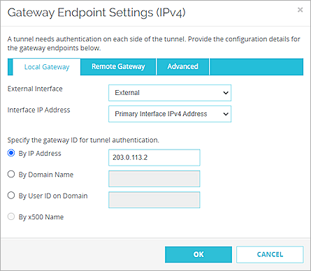
The Gateway Endpoint Settings dialog box opens. - From the External Interface drop-down list, select External.
- From the Interface IP Address drop-down list, select Primary Interface IPv4 Address.
The Primary Interface IP Address is the primary IP address you configured on the selected external interface. - Select By IP Address.
- In the adjacent text box, type the primary IP address of the External Firebox interface..
- Select the Remote Gateway tab.
- Select Static IP Address.
- In the adjacent text box, type the public IP address of the ge-0/0/0.0 interface on the Juniper SRX300.
- Select By IP Address.
- In the adjacent text box, type the public IP address of the ge-0/0/0.0 interface on the Juniper SRX300.
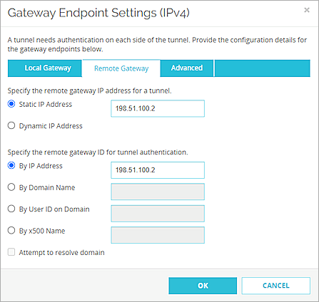
- Click OK.
- In the Gateway Endpoint section, select Start Phase 1 tunnel when Firebox starts.
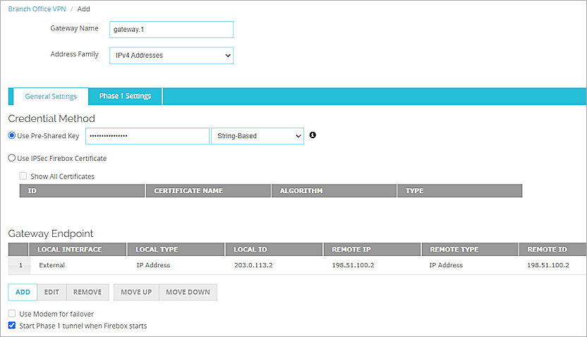
- Select the Phase 1 Settings tab.
- From the Version drop-down list, select IKEv1.
- Keep the default values for all other Phase 1 Settings.
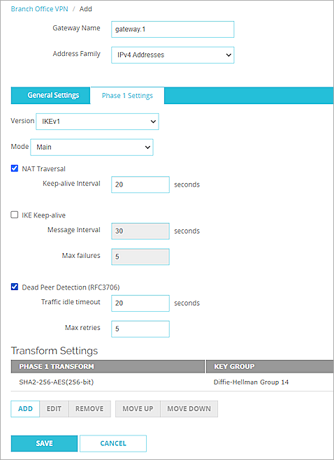
- Click Save.
- In the Tunnels section, click Add.
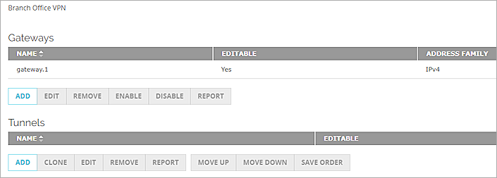
- From the Gateway drop-down list, select the gateway that you configured.
- In the Addresses section, click Add.
- In the Local IP section, from the Choose Type drop-down list, select Network IPv4.
- In the Network IP text box, type the local IP segment. This the local network protected by the Firebox.
- In the Remote IP section, from the Choose Type drop-down list, select Network IPv4.
- In the Network IP text box, type the remote IP segment. This the local network protected by the Juniper device.
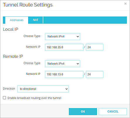
- Click OK.
- Keep the default values for all other Phase 2 Settings.
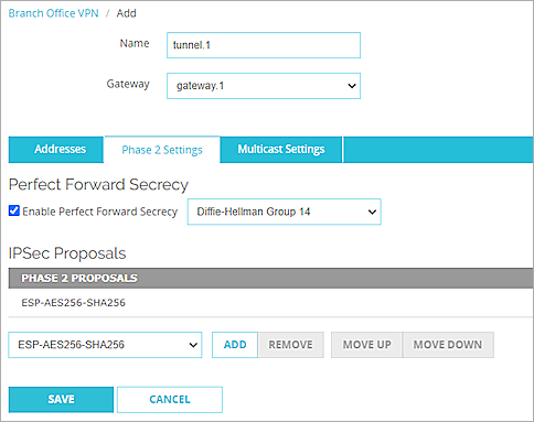
- Click Save.
Configure the Juniper SRX300
Configure Basic Settings
- Log in to the Juniper Web Device Manager at https://<IP address of the Juniper device>.
The default IP address is https://192.168.1.1. - Configure the Juniper interfaces. For information about how to configure interfaces, see the Juniper documentation.
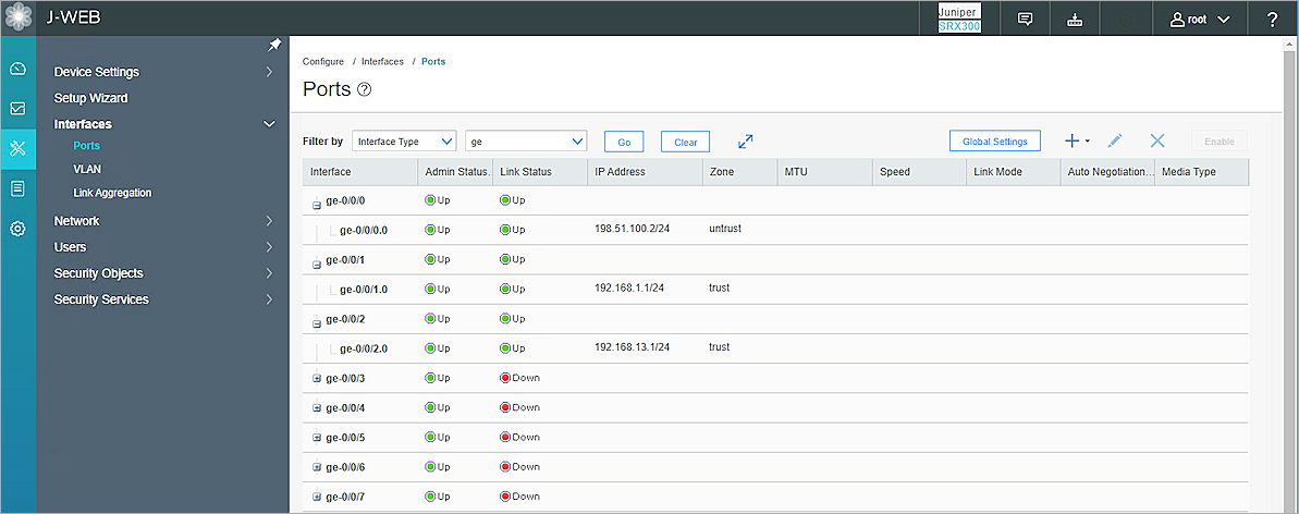
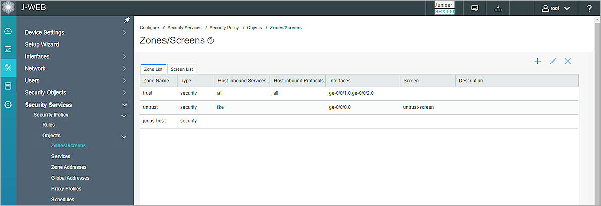
- Configure the zones and bind the zones and interfaces. For information about how to configure zones, see the Juniper documentation.
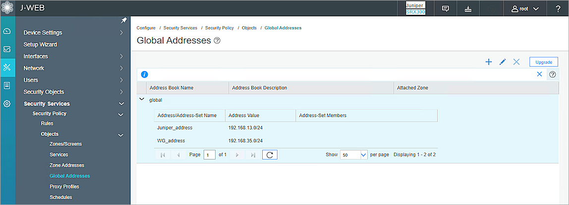
- Configure the global addresses. For information about how to configure global addresses, see the Juniper documentation.
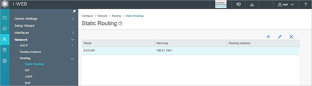
- Configure the static route. For information about how to configure static routes, see the Juniper documentation.
Configure IPSec VPN Phase 1 Settings
On your Juniper device:
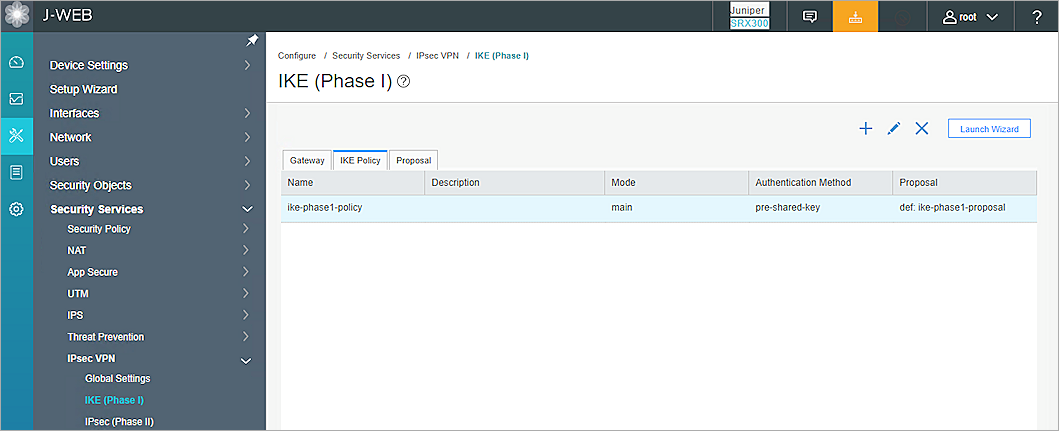
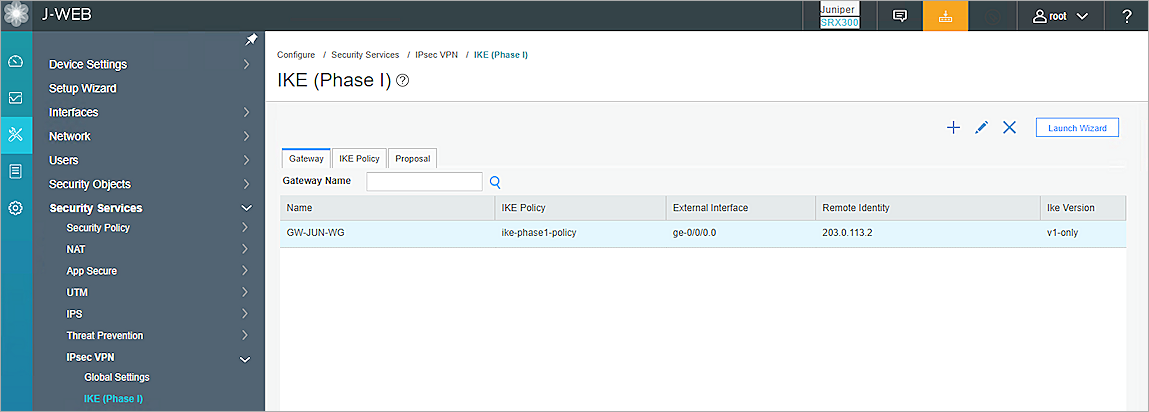
- Select Configure > Security Services > IPsec VPN > IKE (Phase I).
- Select the Proposal tab.
- Click +.
- In Name text box, type a name for the proposal.
- From the Authentication algorithm drop-down list, select sha-256.
- From the Authentication Method drop-down list, select pre-shared-keys.
- From the DH Group drop-down list, select group14.
- From the Encryption algorithm drop-down list, select aes-256-cbc.
- In the Lifetime seconds text box, type the number of seconds.
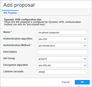
- Click OK.

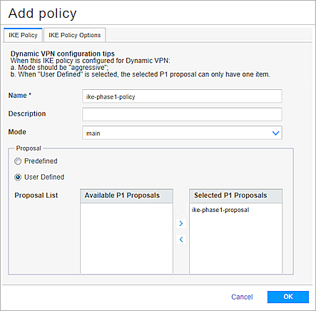
- Select the IKE Policy tab.
- Click +.
- In the Name text box, type a name for the policy.
- From the Mode drop-down list, select main.
- Select User Defined.
- From the Proposal List, select the proposal you created.
- Select the IKE Policy Options tab.
- Select Pre Shared Key.
- Select Ascii text.
- Type the pre-shared key.
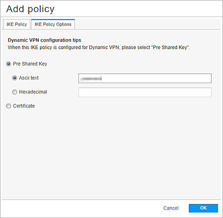
- Click OK.
- Select the Gateway tab.
- Click +.
- In the Name text box, type the gateway name.
- From the Policy drop-down list, select the policy you created.
- From the External Interface drop-down list, select ge-0/0/0.0.
- Select Site to Site VPN.
- In the Remote Peer IP text box, type the IP address of the external Firebox interface.
- Click +.
- From the Local Identity Type drop-down list, select IP Address.
- In the IP Address text box, type the public IP address of Juniper.
- From the Remote Identity Type drop-down list, select IP Address.
- In the IP Address text box, type the public IP address of Firebox.
- From the IKE Version drop-down list, select v1-only.
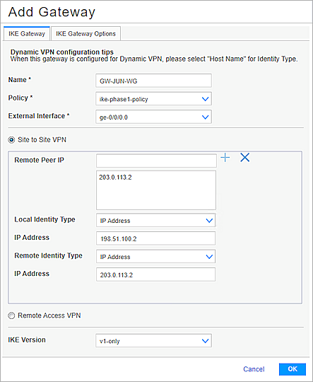
- Click OK.
- To commit the changes, in the upper-right corner, click the
 button.
 - Click Commit.
Configure IPsec VPN Phase 2 Settings
On your Juniper device:
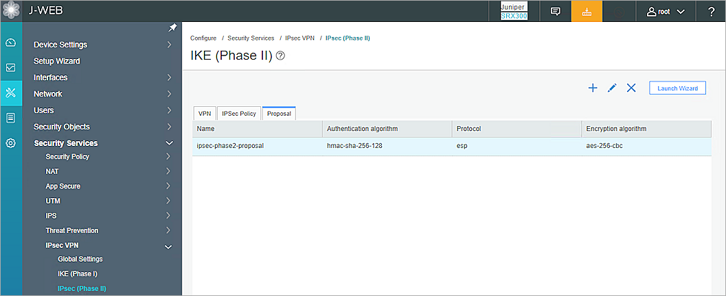
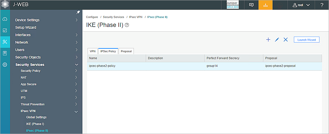
- Select Configure > Security Services > IPsec VPN > IPsec (Phase II).
- Select the Proposal tab.
- Click +.
- In the Name text box, type the proposal name.
- From the Authentication algorithm drop-down list, select hmac-sha-256-128.
- From the Encryption algorithm drop-down list, select aes-256-cbc.
- From the Protocol drop-down list, select esp.
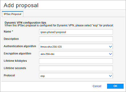
- Click OK.
- Select the IPSec Policy tab.
- Click +.
- In the Name text box, type the policy name.
- From the Perfect Forward Secrecy drop-down list, select group14.
- Select User Defined.
- From the Proposal List, select the proposal you created.
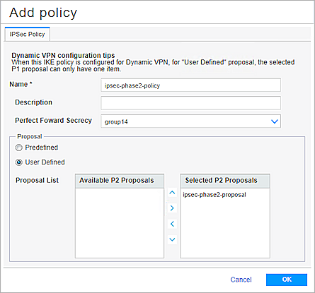
- Click OK.
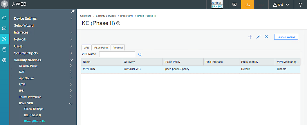
- Select the VPN tab.
- Click +.
- In the VPN Name text box, type the VPN name.
- From the Remote Gateway drop-down list, select GW-JUN-WG.
- From the IPSec Policy drop-down list, select ipsec-phase2-policy.
- From the Bind to tunnel interface drop-down list, select none.
- From the Establish tunnels drop-down list, select immediately.
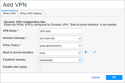
- Click OK.
- To commit the changes, in the upper-right corner, click the button, and click Commit.
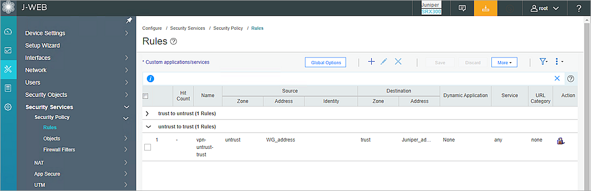
Configure Security Policy rules
- Select Configure > Security Services > Security Policy > Rules.
- Click +.
- In the Rule name text box, type the rule name (for example, vpn-trust-untrust).
- Click Next.
- From the Zone drop-down list, select trust.
- In the Address (es) text box, select Juniper_address.
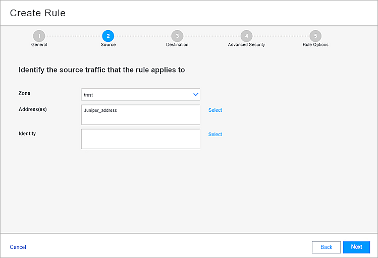
- Click Next.
- From the Zone drop-down list, select untrust.
- In the Address(es) text box, select WG_address.
- In the Dynamic Applicationtext box, select None.
- In the Service(s) text box, select any.
- In the URL Category text box, select None.
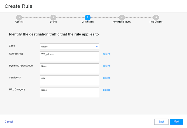
- Click Next.
- From the Rule Action drop-down list, select Permit.
- From the IPSec VPN drop-down list, select VPN-JUN.
- In the Pair Policy Name text box, type the pair policy name (for example, vpn-untrust-trust).
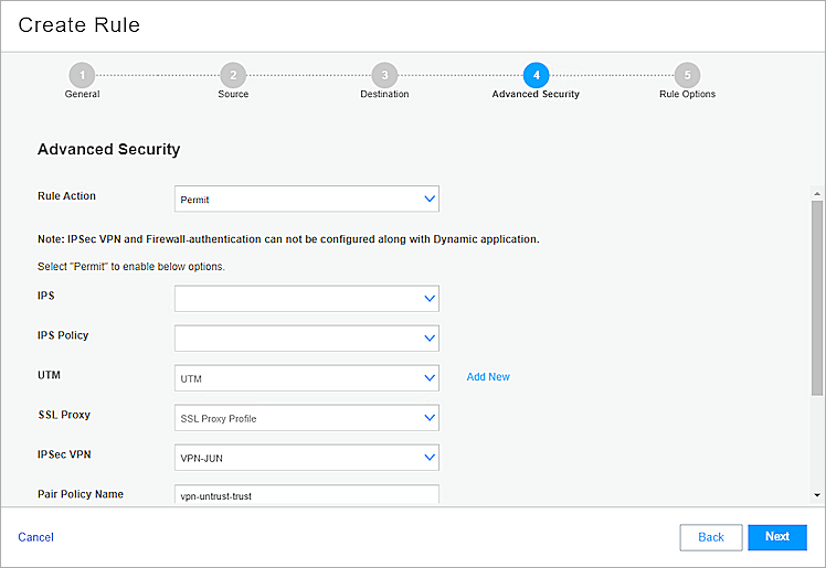
- Click Next.
- Click Finish.
- Click OK.
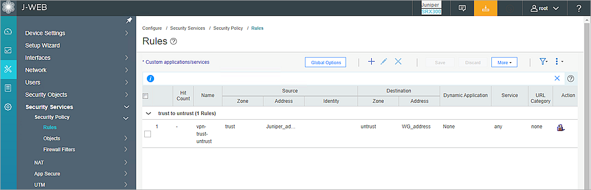
- To create another security policy, repeat steps 2 through 19.
- To commit the changes, in the upper-right corner, click the button.
- Click Commit.
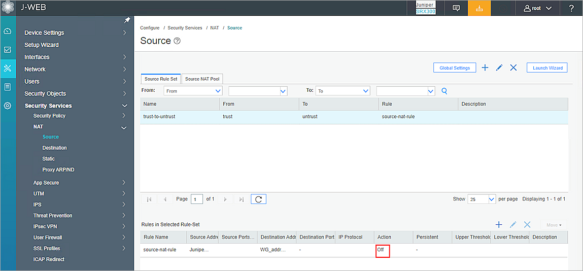
Configure Source NAT
- Select Configure > Security Services > NAT > Source.
- Select the Source Rule Set tab.
- In the Rules in Selected Rule-Set section, select the rule name and click the edit button.
- In the Source Address and Ports section, select Juniper_address.
- In the Destination Address and Ports section, select WG_address.
- For Port, select Any.
- In the Action section, select No Source NAT.
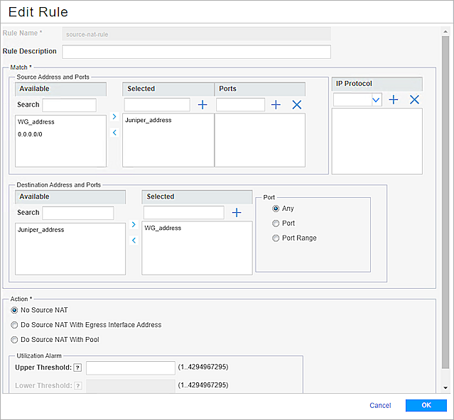
- Click OK.
- To commit the changes, in the upper-right corner, click the button.
- Click Commit.
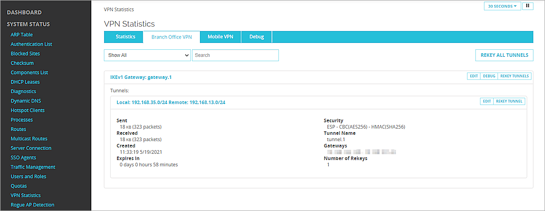
Test the Integration
To test the integration, from Fireware Web UI:
- Select System Status > VPN Statistics.
- Select the Branch Office VPN tab.
- Verify that the VPN is established.
- Verify that Host 1 (behind the Firebox) and Host 2 (behind the Juniper SRX300) can successfully ping each other.