This integration guide describes how to configure a policy-based Branch Office VPN (BOVPN) tunnel between a WatchGuard Firebox and a Fortinet FortiGate 60E. This integration establishes two separate subnets under each firewall device. We require dedicated one-to-one connectivity between paired subnets, not one-to-many access.
Contents
Integration Summary
The hardware and software used in this guide include:
- Firebox with Fireware v12.11 or higher
- Fortinet FortiGate 60E with FortiOS v7.4.7 or higher
Integration Topology
This diagram shows the topology for a BOVPN connection between a Firebox and a Fortinet FortiGate 60E.

Before You Begin
Before you begin these procedures, make sure that:
- If you want to use a cloud-managed Firebox, you have a WatchGuard Cloud account and have added the Firebox to WatchGuard Cloud as a cloud-managed device. You also have configured an external network with the external (public) IP address of the Firebox and two different internal subnets on the Firebox
- If you want to use a locally-managed Firebox, you have configured an external interface with the external (public) IP address of the Firebox and two different internal interfaces on the Firebox.
- You have configured the external interface (wan1) and the internal interfaces (internal2 and internal4) on the FortiGate 60E. For more information about how to configure interfaces, go to the Fortinet User Guide.
Configure the Firebox
You can configure your Firebox for a policy-based BOVPN from WatchGuard Cloud for a cloud-managed Firebox or Fireware Web UI for a locally-managed Firebox.
- Log in to WatchGuard Cloud.
If you log in with a Service Provider account, you must select a Subscriber account from the Account Manager. - Select the cloud-managed Firebox.
- Select Configure > VPNs.
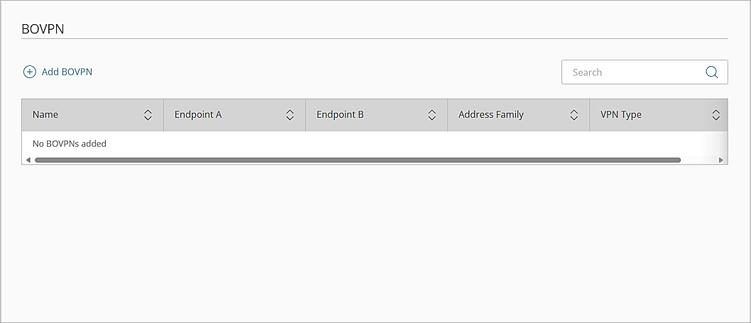
The BOVPN page opens. - Click Add BOVPN.
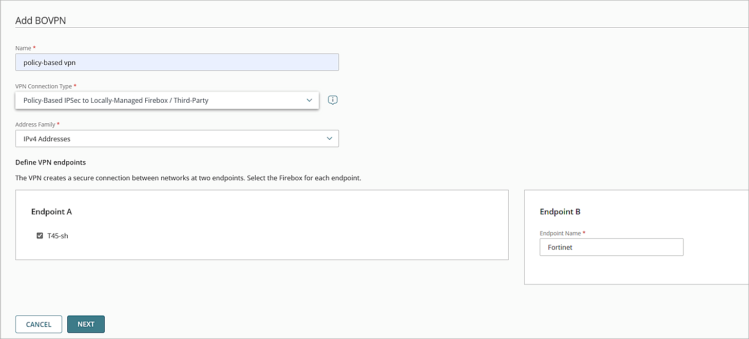
The Add BOVPN page opens. - In the Name text box, type a descriptive name for the BOVPN. In this example, we type policy-based vpn.
- From the VPN Connection Typedrop-down list, select Policy-Based IPSec to Locally-Managed Firebox / Third-Party.
- From the Address Family drop-down list, select IPv4 Addresses.
- In the Endpoint A section, select your cloud-managed firebox.
- In the Endpoint B section, in the Endpoint Name text box, type a name to identify the remote VPN endpoint. In our example, we type Fortinet.
- Click Next.
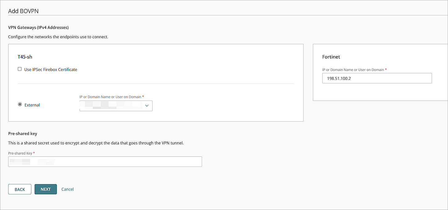
The VPN Gateways settings page opens. - For the cloud-managed Firebox, from theIP or Domain Name or User on Domain drop-down list, select an IP address, domain name, or user on domain that resolves to the Firebox external network IP address.
- For the remote VPN endpoint, in the IP or Domain Name or User on Domain text box, type the public IP address of the FortiGate 60E WAN interface.
- To encrypt and decrypt the data that goes through the VPN tunnel, in the Pre-Shared Key text box, type a shared secret.
- Click Next.
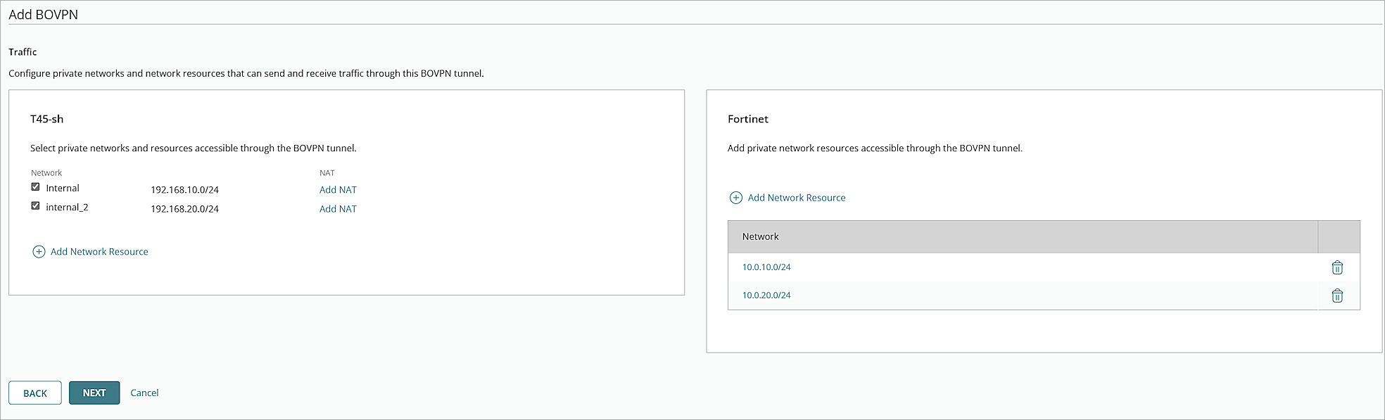
The Traffic settings page opens. - For your cloud-managed Firebox, select the internal networks that you want to be accessible through the VPN tunnel.
- For the Fortinet VPN endpoint, click Add Network Resource.
- Type the IP address of the private network protected by the Fortinet firewall, then click Add.
- If you have multiple private networks protected by the Fortinet firewall, repeat Steps 16–17 to add them.
- Click Next.
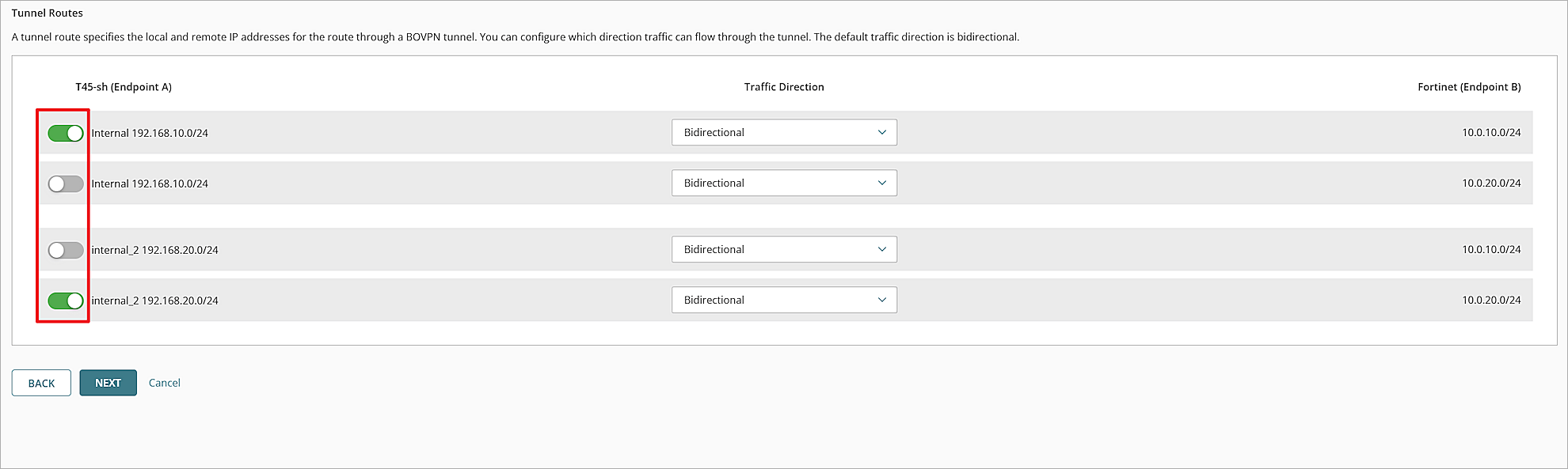
The Tunnel Routes page opens. - If there are tunnel routes you do not want to use in your BOVPN tunnel, use the toggles to disable them.
- Click Next.
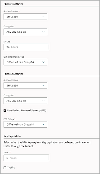
The settings page opens. - Keep the default values for all security settings.
- Click Add.
- Click Finish.
- Log in to Fireware Web UI at: https://<your Firebox IP address>:8080.
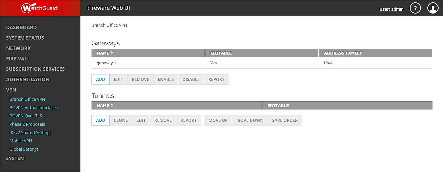
- Select VPN > Branch Office VPN.
The Branch Office VPN configuration page opens. - In the Gateways section, click Add.
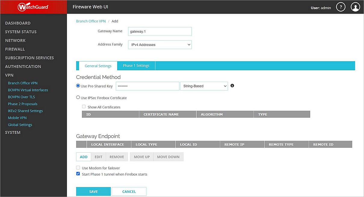
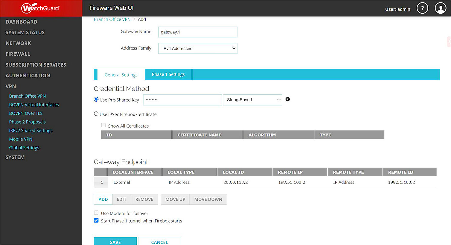
The Add Branch Office VPN page opens. - In the Gateway Name text box, type a name to identify this BOVPN gateway. In this example, we type gateway.1.
- From the Address Family drop-down list, select IPv4 Addresses.
- In the Credential Method section:
- Select Use Pre-Shared Key.
- In the Use Pre-Shared Key text box, type the pre-shared key.
- From the drop-down list, select String-Based.
- Select Use Pre-Shared Key.
- In the Gateway Endpoint section, click Add.
The Gateway Endpoint Settings dialog box opens. - From the External Interface drop-down list, select the interface that has the external (public) IP address of the Firebox.
- From the Interface IP Address drop-down list, select Primary Interface IPv4 Address.
The Primary Interface IP Address is the primary IP address you configured on the selected external interface. - For Specify the Gateway ID for Tunnel Authentication, select By IP Address.
- In the adjacent text box, type the primary IP address of the Firebox external interface. In this example, we type 203.0.113.2.
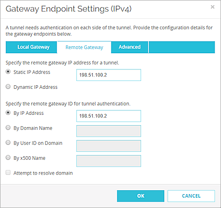
- Select the Remote Gateway tab.
The Remote Gateway page opens. - For Specify the Remote Gateway IP Address for a Tunnel, select Static IP Address.
- In the adjacent text box, type the IP address of your Fortinet WAN connection. In this example, we type 198.51.100.2.
- For Specify the Remote Gateway ID for Tunnel Authentication, select By IP Address.
- In the adjacent text box, type the IP address of your Fortinet WAN connection. In this example, we type 198.51.100.2
- Keep the default values for all other settings.
- Click OK.
The gateway you added appears in the Gateway Endpoint section. - In the Gateway Endpoint section, select the Start Phase 1 Tunnel When Firebox Starts check box.
- Select the Phase 1 Settings tab.
The Phase 1 Settings page opens. - From the Version drop-down list, select IKEv2.
- Keep all default values for all other Phase 1 settings.
- Click Save.
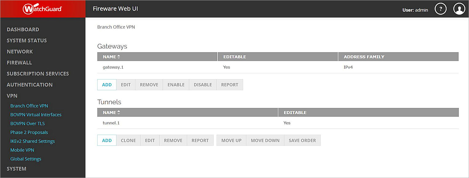
The gateway you added appears on the Branch Office VPN page. - In the Tunnels section, click Add.
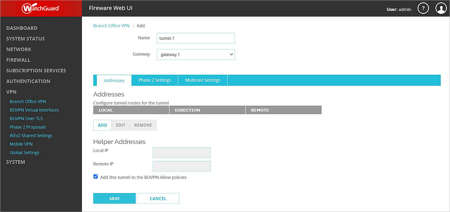
The tunnel settings page opens. - In the Name text box, type a name to identify this tunnel. In this example, we type tunnel.1.
- From the Gateway drop-down list, select the gateway you just created. In this example, we select gateway.1.
- In the Addresses section, click Add.
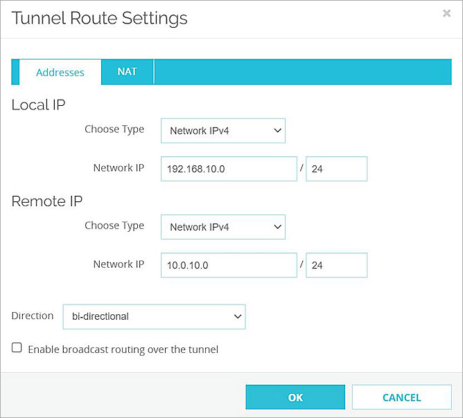
The Tunnel Route Settings dialog box opens. - In the Local IP section:
- From the Choose Type drop-down list, select Network IPv4.
- In the Network IP text box, type the local IP address. This IP address is the internal network that the Firebox protects. In this example, we type 192.168.10.0.
- In the Remote IP section:
- From the Choose Type drop-down list, select Network IPv4.
- In the Network IP text box, type the remote IP address. This IP address is the internal network that the Fortigate protects. In this example, we type 10.0.10.0.
- Click OK.
- To add other internal networks to the VPN, repeat Steps 25–29.
- Keep the default values for all Phase 2 settings.
- Click Save.


Configure the FortiGate 60E
To configure FortiGate 60E, follow these steps:
- Enable Policy-Based VPN
- Configure an IPSec VPN Tunnel
- Configure a BOVPN Policy
- Configure a BOVPN Route (Optional)
Enable Policy-Based VPN
To enable policy-based VPN, from the FortiGate 60E Web UI:
- Log in to the FortiGate 60E Web UI at: https://<IP address of FortiGate 60E>. The default IP address is 192.168.1.99.
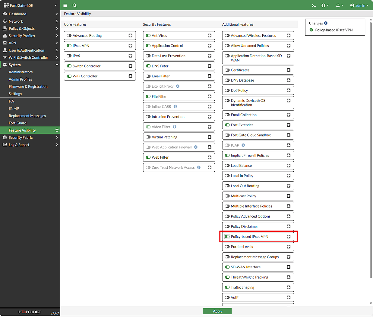
- From the navigation menu, select System > Feature Visibility.
The Feature Visibility page opens. - In the Additional Features list, enable Policy-Based IPsec VPN.
- Click Apply.
Configure an IPSec VPN Tunnel
To configure an IPSec VPN tunnel, from the FortiGate 60E Web UI:
- Log in to the FortiGate 60E Web UI at: https://<IP address of FortiGate 60E>.
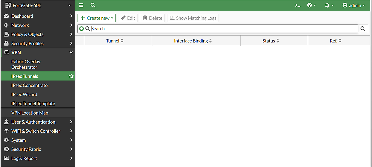
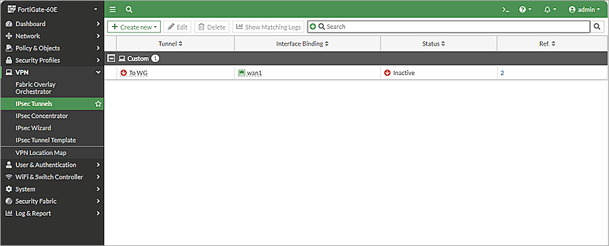
- Select VPN > IPsec Tunnels.
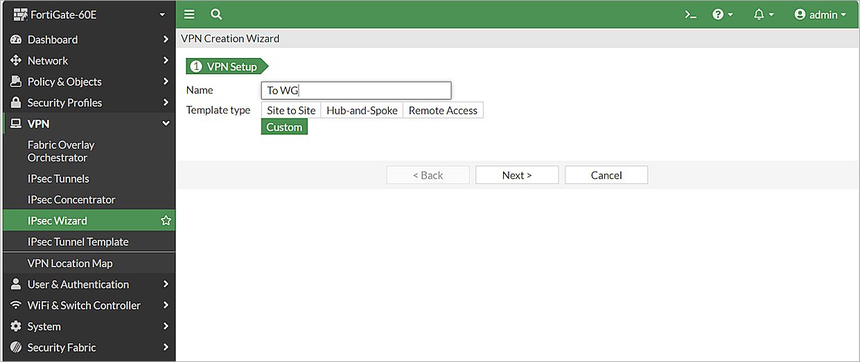
The list of existing tunnels appears. - Click Create New > IPsec Tunnel.The VPN Creation Wizard page opens.
- In the Name text box, type a name for the IPSec VPN tunnel. In this example, we type To WG.
- To continue without a template, for Template Type, select Custom.
- Click Next.
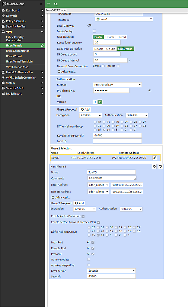
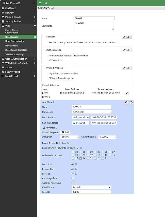
The New VPN Tunnel page opens. - Clear the Enable IPsec Interface Mode check box.
- In the Network section:
- From the Remote Gateway drop-down list, select Static IP Address.
- In the IP Address text box, type the public IP address of the Firebox. In our example, the IP address is 203.0.113.2.
- From the Interface drop-down list, select wan1. Leave the default value for all other settings in the Network section.
- In the Authentication section:
- From the Method drop-down list, select Pre-Shared Key.
- In the Pre-Shared Key text box, type the pre-shared key.
- In the IKE section, for Version, select 2.
- In the Phase 1 Proposal section:
- Remove all proposals except AES256 for encryption and SHA256 for authentication.
- For Diffie-Hellman Group, select 14. Clear all other check boxes.
- Keep the default values for all other Phase 1 settings.
- In the Phase 2 Selectors > New Phase 2 section:
- From the Local Address drop-down list, select Subnet.
- Type the local IP segment. This IP address is the internal network that the VPN protects.
- From the Remote Address drop-down list, select Subnet.
- Type the remote IP segment. This IP address is the internal network that the VPN protects.
- Click Advanced.
The Phase 2 Proposal settings appear. - Remove all proposals except AES256 for encryption and SHA256 for authentication.
- Select the Enable Replay Detection check box.
- Select the Enable Perfect Forward Secrecy (PFS) check box.
- For Diffie-Hellman Group, select 14and clear all other check boxes.
- Leave the default value for all other Phase 2 settings.
- Click OK.
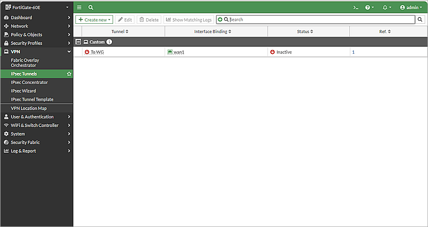
The tunnel you added appears in the list of existing tunnels. - To edit the IPSec tunnel you added, select the tunnel and click Edit.
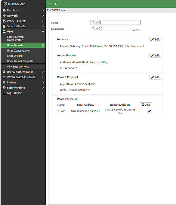
The Edit VPN Tunnel page opens. - In the Phase 2 Selectors section, click Add.
- To create a new Phase 2 for another subnet, repeat Steps 14–18.
- Click OK.

Configure a BOVPN Policy
To configure a BOVPN policy, from FortiGate 60E Web UI:
- Log in to the FortiGate 60E Web UI at: https://<IP address of FortiGate 60E>.
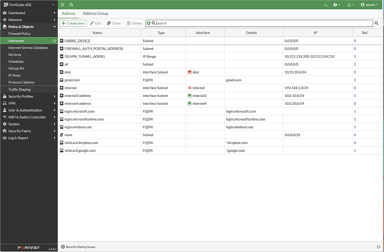
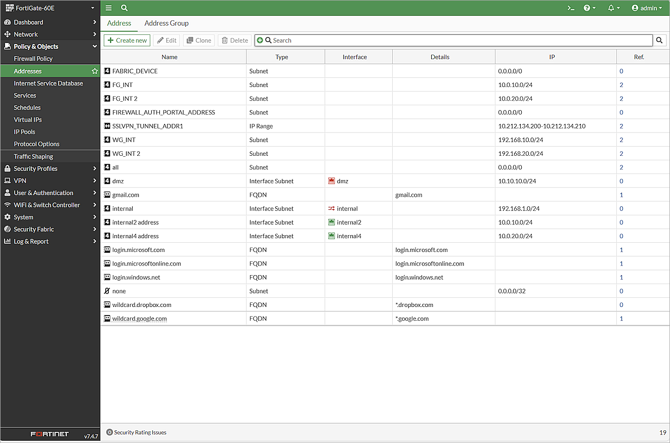
- Select Policy & Objects > Addresses.
The Address page opens. - Click Create New.
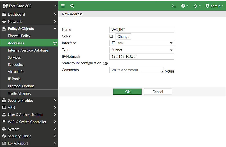
The New Address page opens. - In the Name text box, type a name for the subnet behind the Firebox. In this example, we type WG_INT.
- From the Type drop-down list, select Subnet.
- In the IP/Netmask text box, type the IP address of the subnet behind the Firebox. In this example, we type 192.168.10.0/24.
- Keep the default values for all other settings.
- Click OK.
- To add more subnets in the policy, repeat Steps 3–8.
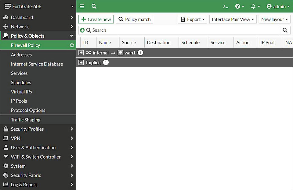
- From the navigation menu, select Policy & Objects > Firewall Policy.
The list of firewall policies opens. - Click Create New.
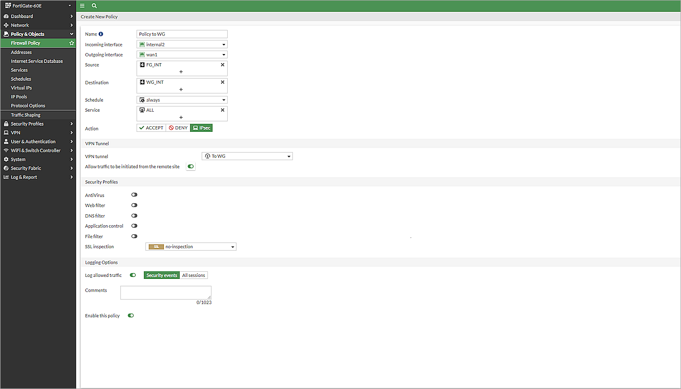
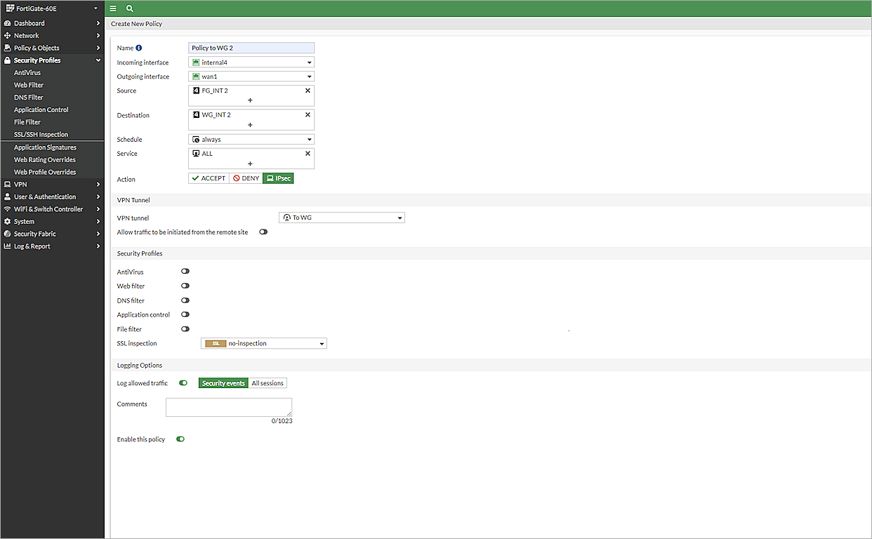
The Create New Policy page opens. - In the Name textbook, type a name for this policy. In this example, we type Policy to WG.
- From the Incoming Interface drop-down list, select internal2.
- From the Outgoing Interface drop-down list, select wan1.
- From the Source drop-down list, select FG_INT.
- From the Destination drop-down list, select the address name you typed in Step 4. In this example, we select WG_INT.
- From the Schedule drop-down list, select Always.
- From the Service drop-down list, select All.
- For Action, select IPsec.
- From the VPN Tunnel drop-down list, select the VPN Tunnel you created inConfigure an IPSec VPN Tunnel. In this example, we select To WG.
- Enable Allow Traffic to Be Initiated From the Remote Site.
- Keep the default values for all other settings.
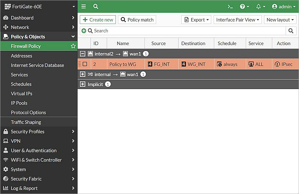
- Click OK.
The policy you created appears in the list of policies. - To create another policy for another subnet, repeat Steps 11–23.
Configure a BOVPN Route (Optional)
If you have not configured a gateway for the wan1 interface, you must add a route manually.
To configure a route, from the FortiGate 60E Web UI:
- Log in to the FortiGate 60E Web UI at: https://<IP address of FortiGate 60E>
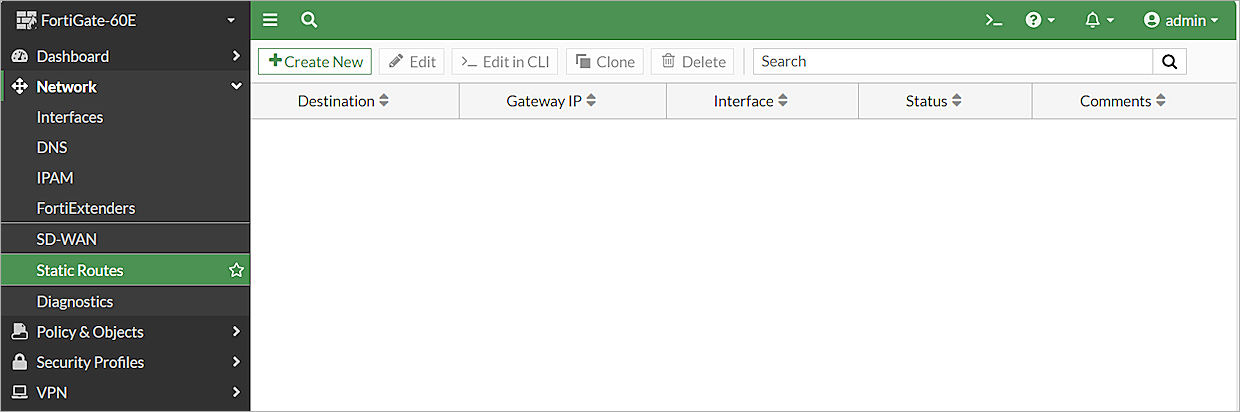
- From the navigation menu, select Network > Static Routes.
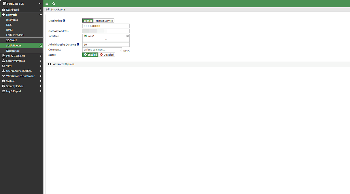
The list of static routes opens. - Click Create New.
The Edit Static Route page opens. - In the Destination > Subnet text box, type 0.0.0.0/0.0.0.0.
- In the Gateway Address text box, type the IP address for your wan1 gateway.
- From the Interface drop-down list, select wan1.
- Keep the default values for all other settings.
- Click OK.
Test the Integration
- Log in to WatchGuard Cloud.
If you log in with a Service Provider account, you must select a Subscriber account from the Account Manager. - Select the cloud-managed Firebox.
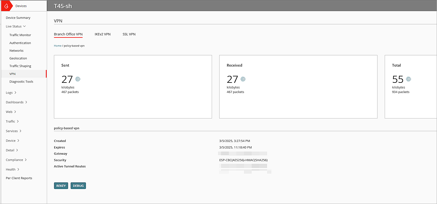
- Select Monitor > Live Status > VPN.
The VPN page opens. - Click the BOVPN you configured.
- Verify that the two VPN tunnels are active.
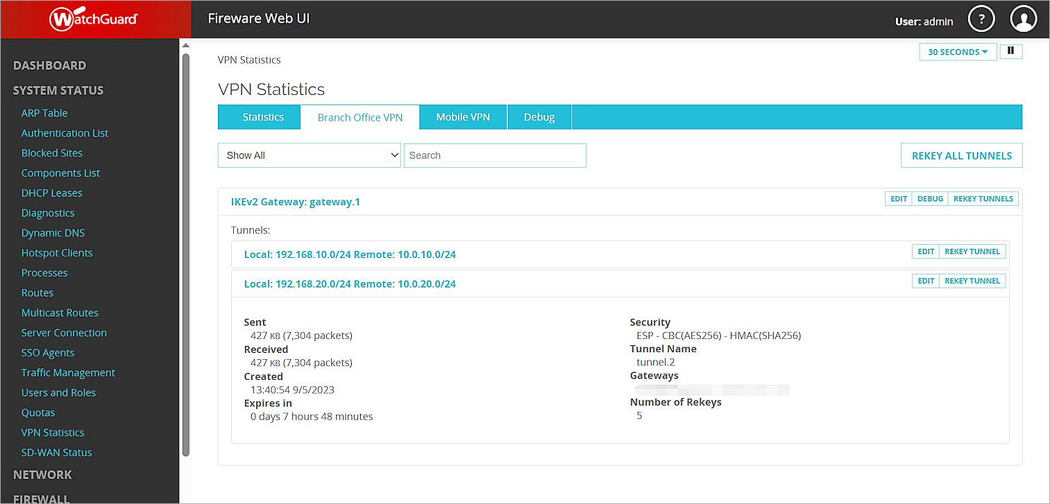
- Log in to Fireware Web UI at: https://<your Firebox IP address>:8080.
- Select System Status > VPN Statistics.
The VPN Statistics page opens. - Select the Branch Office VPN tab.
The Branch Office VPN page opens. - In the Tunnels section, verify that the two VPN tunnels are active.
- Log in to the FortiGate 60E Web UI at: https://<IP address of FortiGate 60E>.
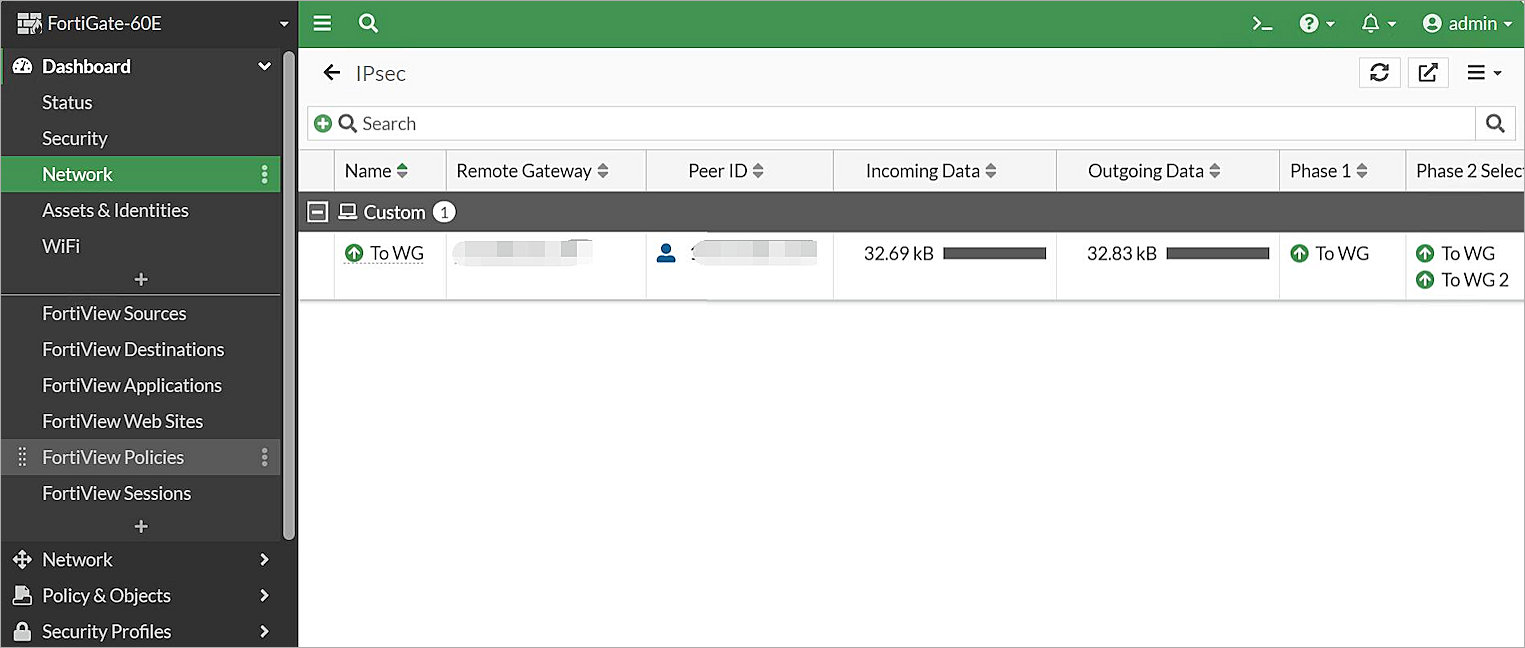
- Select Dashboard > Network > IPsec.
The IPsec page opens. - Verify that the two VPN tunnels you configured are active.
- Verify that Host 1 (behind the Firebox) and Host 2 (behind the FortiGate 60E) can ping each other.