This integration guide describes how to configure a policy-based Branch Office VPN (BOVPN) between a WatchGuard Firebox and a Cisco Firepower 1010E Threat Defense.
Contents
Integration Summary
The hardware and software used in this guide include:
- Firebox with Fireware v12.11.2 or higher
-
Firepower 1010E Threat Defense v7.4.2.2-28 or higher
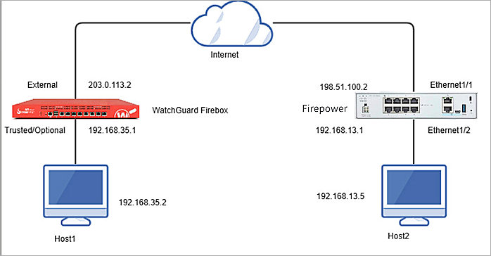
Topology
This diagram shows the topology for a BOVPN connection between a Firebox and a Firepower 1010E.
Before You Begin
Before you begin these procedures, make sure that:
- If you want to use a cloud-managed Firebox, you have a WatchGuard Cloud account and have added the Firebox to WatchGuard Cloud as a cloud-managed device. You also have configured an external network with the external (public) IP address of the Firebox and at least one internal network on the Firebox.
- If you want to use a locally-managed Firebox, you have configured an external interface with the external (public) IP address of the Firebox and at least one internal network on the Firebox.
- You have configured the internal network objects for the Firebox and Firepower in the Firepower 1010E web UI. In this guide, we use the Network_under_Firebox and Network_Under_Firepower network objects.
- You have configured an internal and external interface in the Firepower 1010E web UI. In this guide, we use the external ethernet1/1 and internal ethernet1/2 interfaces. For more information about how to configure interfaces, go to the Cisco Firepower official documentation.
Configure the Firebox
You can configure your Firebox for a policy-based BOVPN from WatchGuard Cloud for a cloud-managed Firebox or Fireware Web UI for a locally-managed Firebox.
- Log in to WatchGuard Cloud.
If you log in with a Service Provider account, you must select a Subscriber account from the Account Manager. - Select Configure > VPNs.
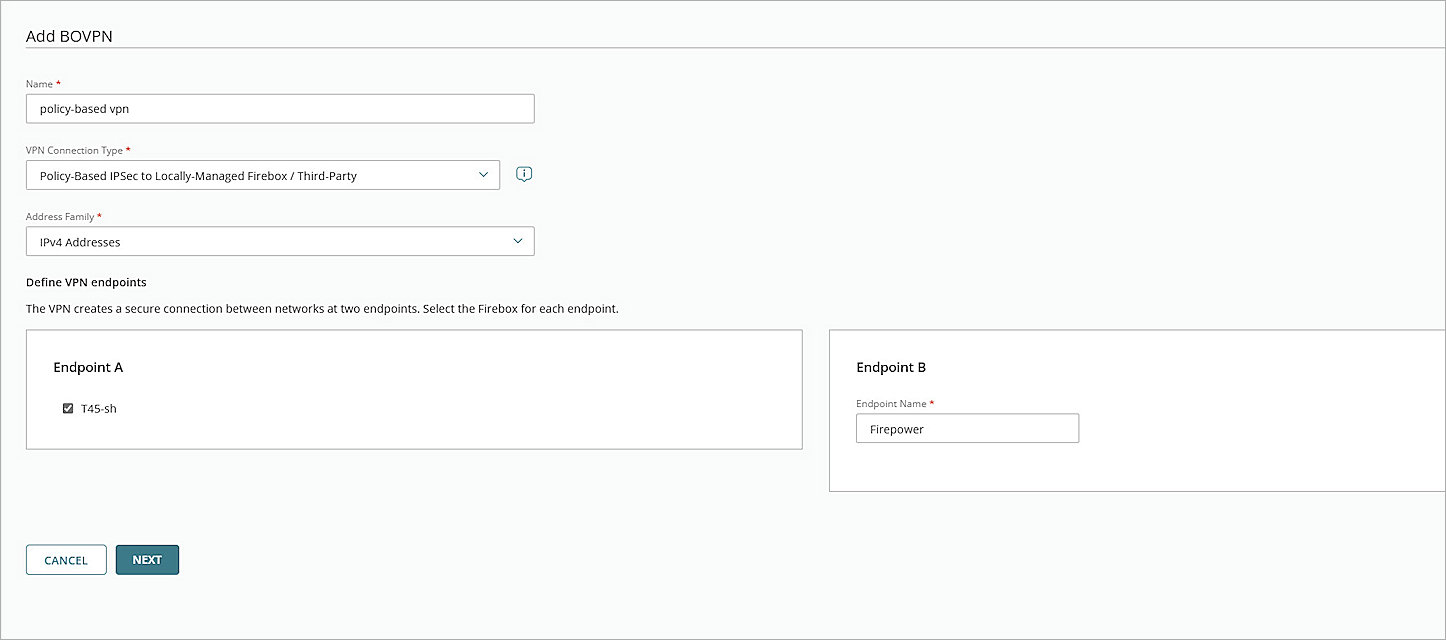
- Click Add BOVPN.
The Add BOVPN page opens. - In the Name text box, type a descriptive name for the BOVPN. In this example, we type policy-based vpn.
- From the VPN Connection Type drop-down list, select Policy-Based IPSec to Locally-Managed Firebox / Third-Party.
- From the Address Family drop-down list, select IPv4 Addresses.
- In the Endpoint A section, select your cloud-managed Firebox.
- In the Endpoint B section, in the Endpoint Name text box, type a name to identify the remote VPN endpoint. In our example, we type Firepower.
- Click Next.
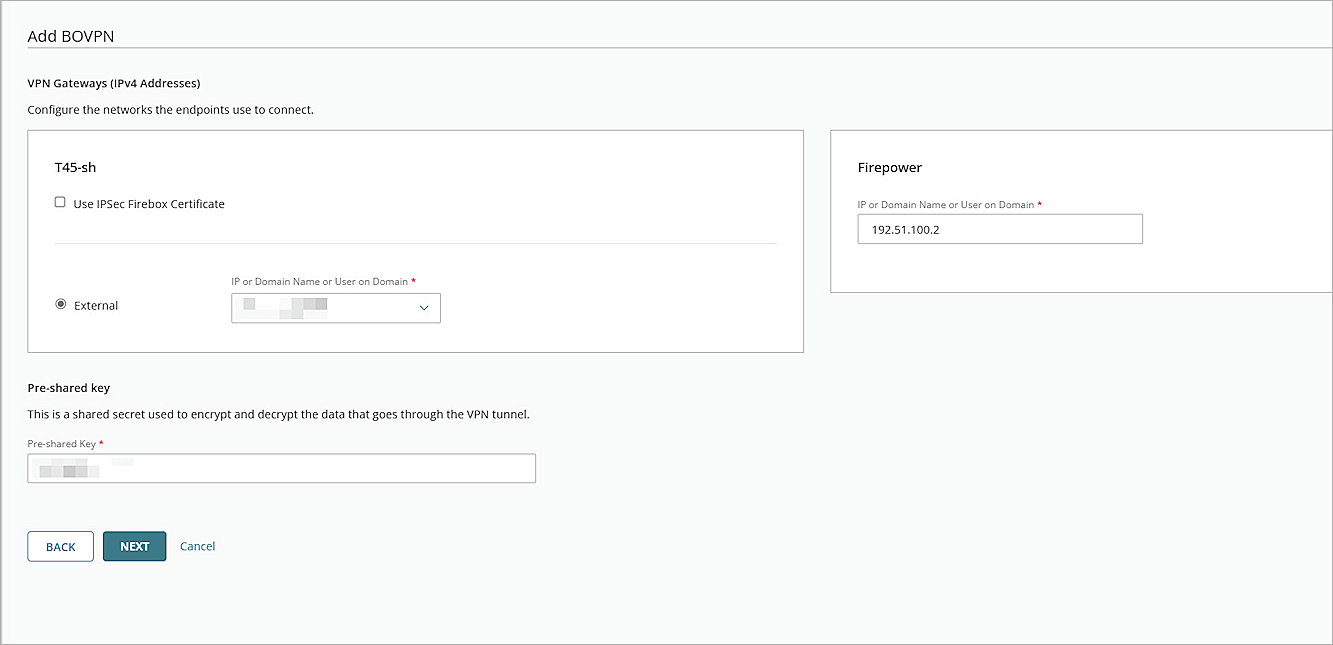
The VPN Gateway settings page opens. - For your cloud-managed Firebox:
- Select External.
- From the IP or Domain Name or User on Domain text box, select an IP address, domain name, or user on domain that resolves to the Firebox external network IP address.
- For the remote VPN endpoint, in the IP or Domain Name or User on Domain text box, type the IP address of your Firepower firewall WAN connection.
- To encrypt and decrypt the data goes through the VPN tunnel, in the Pre-Shared Key text box, type a pre-shared key. This pre-shared key matches the pre-shared key you will configure for the Firepower IPSec VPN Phase 1 settings.
- Click Next.
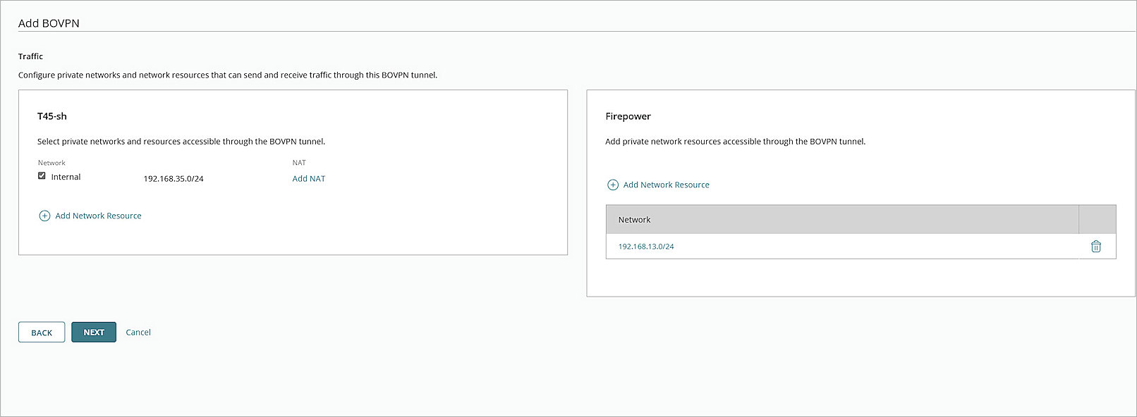
The Traffic settings page opens. - For your cloud-managed Firebox, select the internal network that you want to be accessible through the VPN tunnel.
- For the Firepower endpoint, click Add Network Resource.
- In the Network Resource text box, type the IP address of the private network protected by the Firepower firewall. In our example, we type 192.168.13.0/24.
- Click Add.
- Keep the default values for all other settings.
- Click Next.
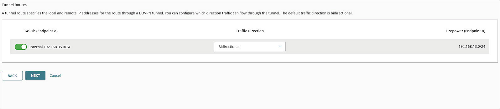
The Tunnel Routes page opens. - Keep the default values for all other settings.
- Click Next.
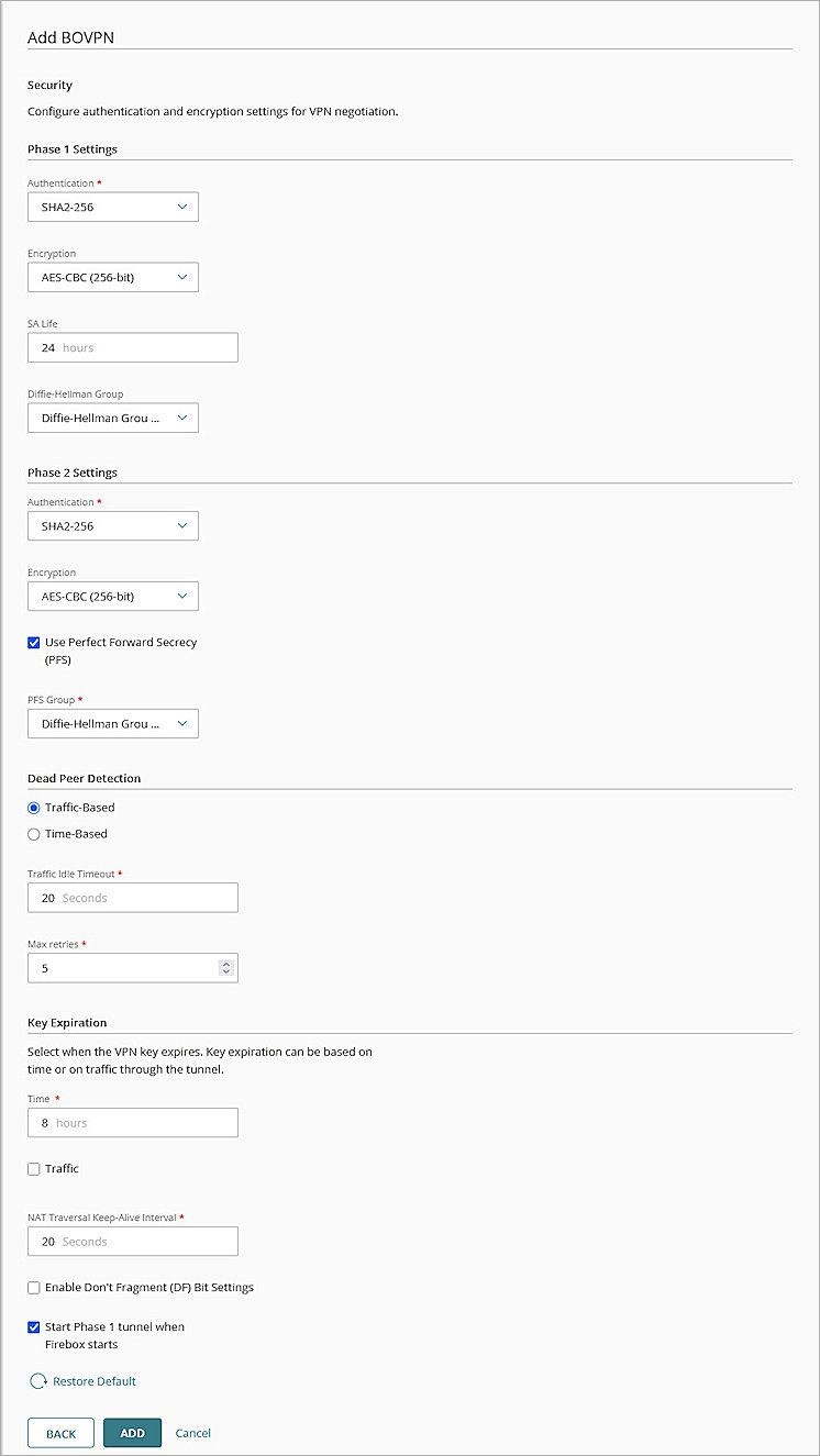
The Security settings page opens. - In the Phase 1 Settings section
- From the Authentication drop-down list, select SHA2-256.
- From the Encryption drop-down list, select AES-CBC (256-bit).
- In the SA Life text box, type 24.
- From the Diffie-Hellman Group drop-down list, select Diffie-Hellman Group14.
- In the Phase 2 Settings section:
- From the Authentication drop-down list, select SHA2-256.
- From the Encryption drop-down list, select AES-CBC (256-bit).
- Select the Use Perfect Forward Secrecy (PFS) check box.
- From the PFS Group drop-down list, select Diffie-Hellman Group14.
- Keep the default values for all other settings.
- Click Add.
- (Optional) To open the VPN Configuration Summary page for the cloud-managed Firebox, click View Guide.
- Click Finish.
WatchGuard Cloud creates and deploys a configuration update for the cloud-managed Firebox.
- Log in to Fireware Web UI at https://<your Firebox IP address>:8080.
- Select VPN > Branch Office VPN.
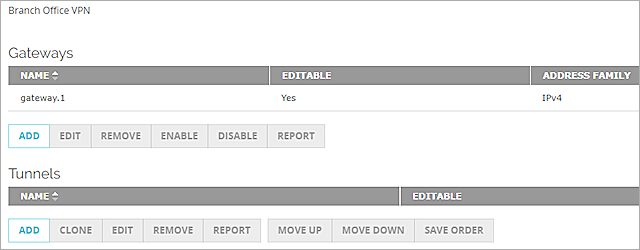
The Branch Office VPN configuration page opens. - In the Gateways section, click Add.
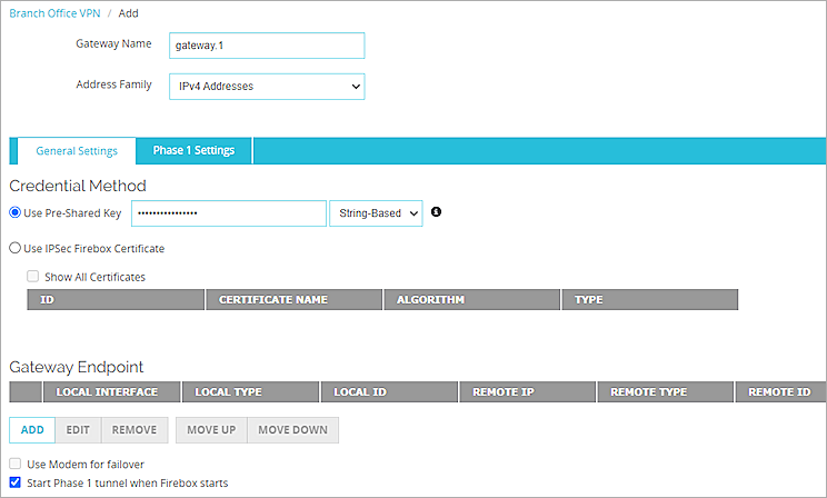
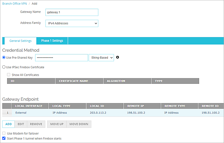
The Add page opens. - In the Gateway Name text box, type a name to identify this BOVPN gateway. In this example, we type gateway.1.
- From the Address Family drop-down list, select IPv4 Addresses.
- In the Credential Method section:
- Select Use Pre-Shared Keyand in the adjacent text box, type the pre-shared key.
- From the drop-down list, select String-Based.
- In the Gateway Endpoint section, click Add.
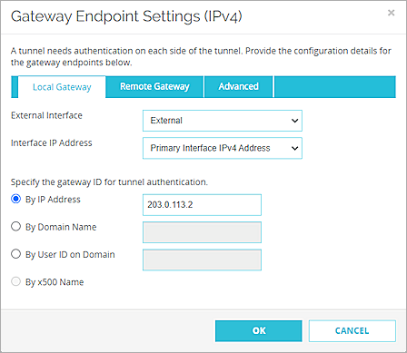
The Gateway Endpoint Settings dialog box opens. - From the External Interface drop-down list, select the interface that has the external (public) IP address of the Firebox.
- From the Interface IP Address drop-down list, select Primary Interface IPv4 Address.
The Primary Interface IP Address is the primary IP address you configured on the selected external interface. - For Specify the Gateway ID for Tunnel Authentication, select By IP Address.
- In the adjacent text box, type the primary IP address of the external Firebox interface. In this example, we type 203.0.113.2.
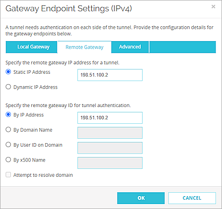
- Select the Remote Gateway tab.
The Remote Gateway page opens. - For Specify the Remote Gateway IP Address for a Tunnel, select Static IP Address.
- In the adjacent text box, type the IP address of your Firepower WAN connection. In this example, we type 198.51.100.2.
- For Specify the Remote Gateway ID for Tunnel Authentication, select By IP Address.
- In the adjacent text box, type the IP address of your Firepower WAN connection. In this example, we type 198.51.100.2.
- Keep the default values for all other settings.
- Click OK.
The gateway endpoint you added appears in the Gateway Endpoint section. - In the Gateway Endpoint section, select the Start Phase 1 Tunnel When Firebox Starts check box.
- Select the Phase 1 Settings tab.
The Phase 1 Settings page opens. - From the Version drop-down list, select IKEv2.
- Keep the default values for all other Phase 1 settings.
- Click Save.
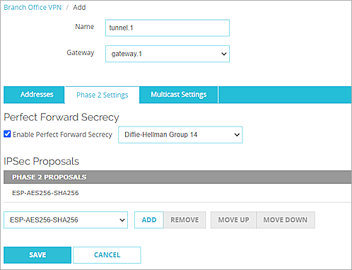
The gateway you added appears on the list of gateways. - In the Tunnels section, click Add.
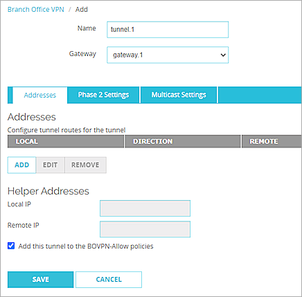
The tunnel settings page opens. - In the Name text box, type a name to identify the tunnel. In this example, we type tunnel.1.
- From the Gateway drop-down list, select the gateway that you configured. In this example, we select gateway.1.
- In the Addresses section, click Add.
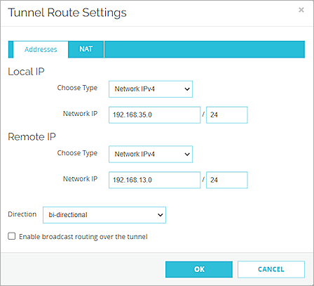
The Tunnel Route Settings page opens. - In the Local IP section:
- From the Choose Type drop-down list, select Network IPv4.
- In the Network IP text box, type the local IP segment. This is the local network protected by the Firebox. In this example, we type 192.168.35.0.
- In the Remote IP section:
- From the Choose Type drop-down list, select Network IPv4.
- In the Network IP text box, type the remote IP segment. This is the local network protected by the Firepower. In this example, we type 192.168.13.0.
- Click OK.
- Keep the default values for all Phase 2 settings.
- Click Save.

Configure the Firepower 1010E
To configure the Firepower 1010E, complete these steps:
- Configure an IPSec VPN Tunnel for the Firepower 1010E
- Configure Policies for the Firepower 1010E
- Deploy the Configuration for the Firepower 1010E
Configure an IPSec VPN Tunnel for the Firepower 1010E
To configure an IPSec VPN tunnel for the Firepower 1010E:
- Log in to the Firepower Web UI at: https://<Management IP address of the Firepower>
- Select Device: [Firepower device name].
- In the Site-to-Site VPN section, click View Configuration.
The Site-to-Site VPN page opens. - Click Create Site-to-Site Connection.
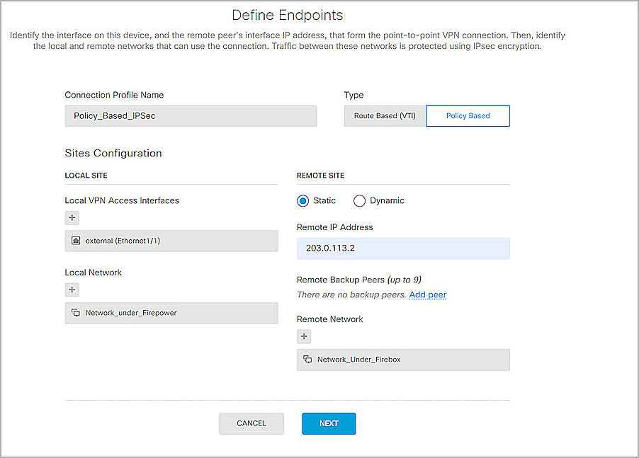
The Define Endpoints page opens. - In the Connection Profile Name text box, type a descriptive name for the VPN. In our example, we type Policy-Based_IPSec.
- For Type, select Policy Based.
- From the Local VPN Access Interfaces drop-list, select the external interface you configured for the Firepower. In our example, we select external (Ethernet1/1).
- From the Local Network drop-list, select the internal network you configured for the Firepower. In our example, we select Network_Under_Firepower.
- In the Remote Site section, select Static.
- In the Remote IP Address text box, type the public IP address for your Firebox. In our example, we type 203.0.113.2.
- From the Remote Network drop-list, select the network object you configured for your Firebox. For our example, we select Network_Under_Firebox.
- Click Next.
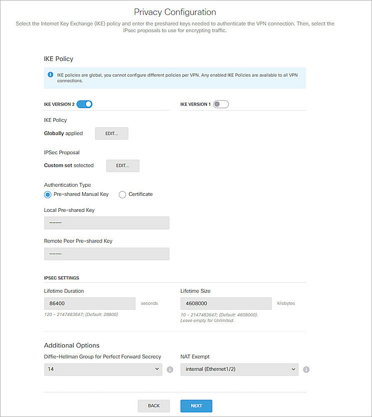
The Privacy Configuration page opens. - Enable IKE Version 2.
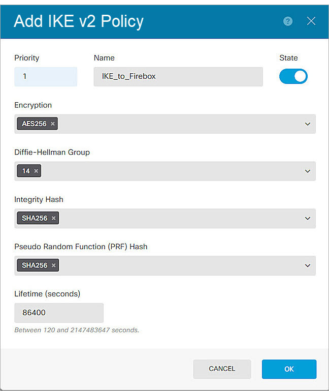
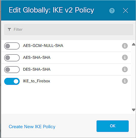
- In the IKE Policy section, click Edit > Create New IKE Policy.
The IKE v2 Policy configuration dialog box opens. - In the Priority text box, type the priority number for the IKE v2 policy. In our example, we type 1.
- In the Name text box, type a descriptive name for the IKE v2 policy. In our example, we type IKE_to_Firebox.
- Enable State.
- From the Encryption drop-down list, select AES 256.
- From the Diffie-Hellman Group drop-down list, select 14.
- From the Integrity Hash drop-down list, select SHA256.
- From the Pseudo Random Function (PRF) Hash drop-down list, select SHA256.
- In the Lifetime (Seconds) text box, type 86400.
- Click OK.
The IKE v2 policy you created appears in the list of policies. - Disable any other IKE v2 policies in the list.
- Click OK.
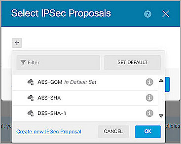
The Select IPSec Proposals dialog box opens. - To create a new IPSec proposal, select Edit > Add IPSec Proposals > Create New IPSec Proposal.
The IKE v2 IPSec Proposal configuration dialog box opens. - In the Name text box, type a descriptive name for the proposal. In our example, we type IKE_to_Firebox_Proposal.
- From the Encryption drop-down list, select AES 256.
- From the Integrity Hash drop-down list, select SHA256.
- Click OK.
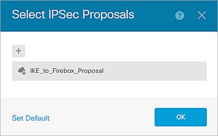
- Select the IKE v2 proposal you created in the previous steps.
- Click OK.
- Click OK.
The Privacy Configuration page opens. - For Authentication Type, select Pre-Shared Manual Key.
- In the Local Pre-Shared Key text box, type the same pre-shared key you configured for the Firebox.
- In the Remote Peer Pre-Shared Key text box, type the same pre-shared key you configured for the Firebox.
- In the Lifetime Duration text box, type 86400.
- In the Additional Options section, from the Diffie-Hellman Group for Perfect Forward Secrecy drop-down list, select 14.
- From the NAT Exempt drop-down list, select the interface to be protected by the VPN tunnel. In our example, we select internal (Ethernet 1/2).
- Click Next.
The Summary page opens. - Verify the configurations on this page, then click Finish.
The VPN is created successfully.
Configure Policies for the Firepower 1010E
To configure policies for the Firepower 1010E:
- Log in to the Firepower Web UI at: https://<Management IP address of the Firepower>.
- Select Policies.
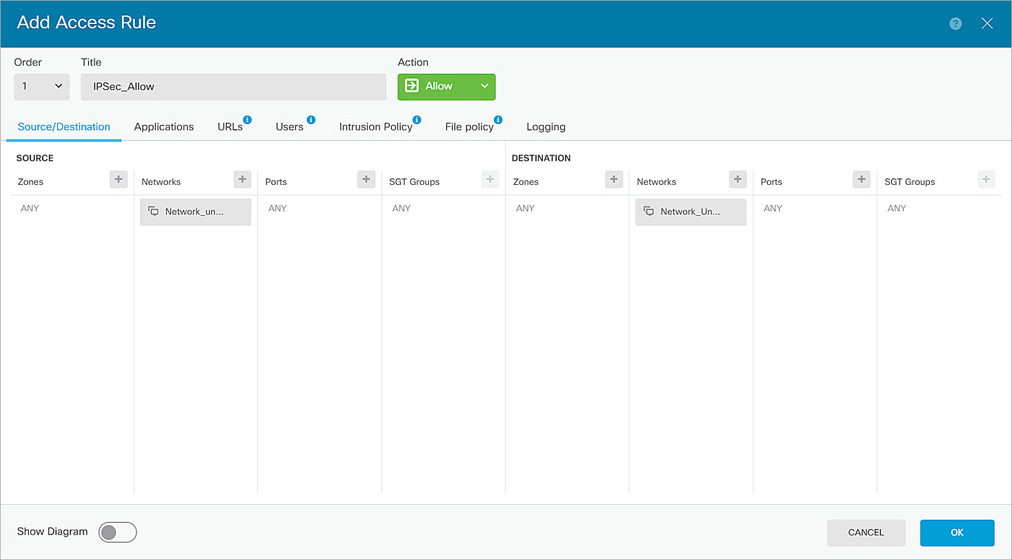
The Policy Configuration page opens. - Click Create Access Rule.
The Add Access Rule dialog box opens. - In the Title text box, type a descriptive name for this policy. In our example, we type IPSec_AllowIPSec_Allow.
- From the Action drop-down list, select Allow.
- In the Source section, from the Networks drop-down list, select the internal network you configured for the Firepower. In our example, we select Network_Under_Firepower.
- In the Destination section, from the Networks drop-down list, select the internal network you configured for the Firebox. In our example, we select Network_Under_Firebox.
- Click OK.
Deploy the Configuration for the Firepower 1010E
To deploy the Firepower 1010E configuration:
- Log in to the Firepower Web UI at: https://<Management IP address of the Firepower>.
- Select Deployment.
- Click Deploy Now.
- Click OK.
It might take several minutes to complete the deployment.
Test the Integration
- Log in to WatchGuard Cloud.
If you log in with a Service Provider account, you must select a Subscriber account from the Account Manager. - Select the cloud-managed Firebox.
- Select Monitor > Live Status > VPN > Branch Office VPN.

- Verify that the VPN tunnels are active.
- Log in to Fireware Web UI at: https://<your Firebox IP address>:8080.
- Select System Status > VPN Statistics.
The VPN Statistics page opens. - Select the Branch Office VPN tab.
The Branch Office VPN page opens.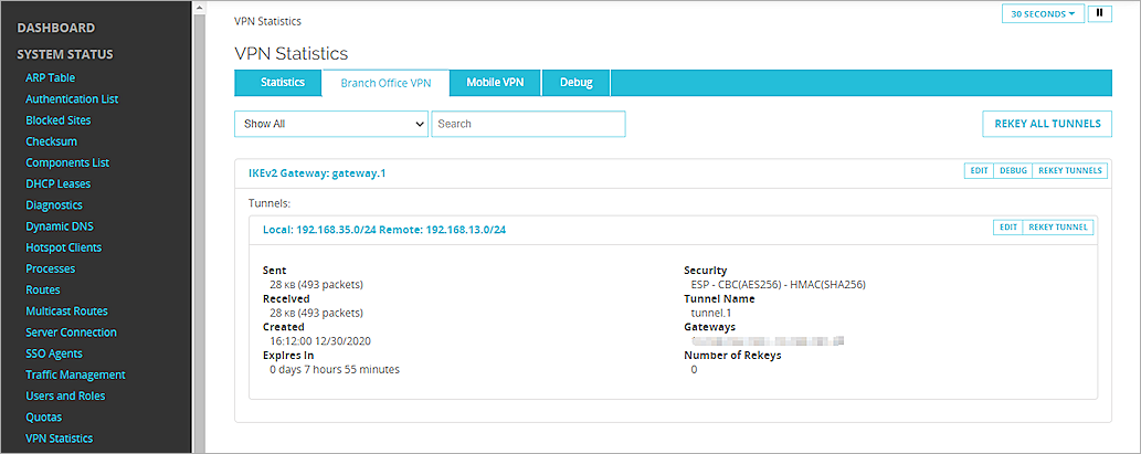
- In the Tunnels section, verify that the VPN tunnels are active.