Deployment Overview
WatchGuard provides integration instructions to help our customers configure WatchGuard products to work with products created by other organizations. If you need more information or technical support about how to configure a third-party product, see the documentation and support resources for that product.
This integration guide describes how to configure a BOVPN virtual interface connection between a WatchGuard Firebox and a Cisco Integrated Services Router (ISR).
Integration Summary
The hardware and software used in this guide include:
- WatchGuard Firebox
- Fireware v12.7.2 or higher
- Cisco ISR C921-4P
- Version 15.9.3M2
Topology
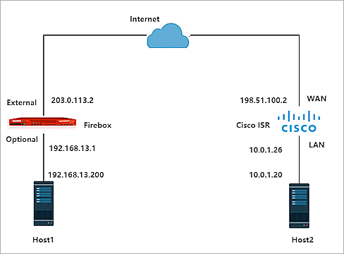
This diagram shows the topology for a BOVPN virtual interface connection between a Firebox and a Cisco ISR.
Configure the Firebox
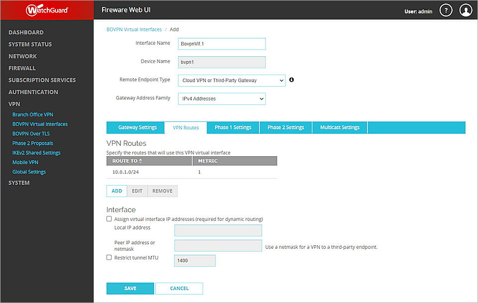
To configure a BOVPN virtual interface, from Fireware Web UI:
- Select VPN > BOVPN Virtual Interfaces.
The BOVPN Virtual Interfaces configuration page opens. - Click Add.
- From the Remote Endpoint Type drop-down list, select Cloud VPN or Third-Party Gateway.
- From the Gateway Address Family drop-down list, select IPv4 Addresses.
- On the Gateway Settings tab, select Use Pre-Shared Key.
- In the adjacent text box, type the pre-shared key.
- In the adjacent drop-down list, select String-Based.
- Enable Start Phase 1 tunnel when it is inactive.
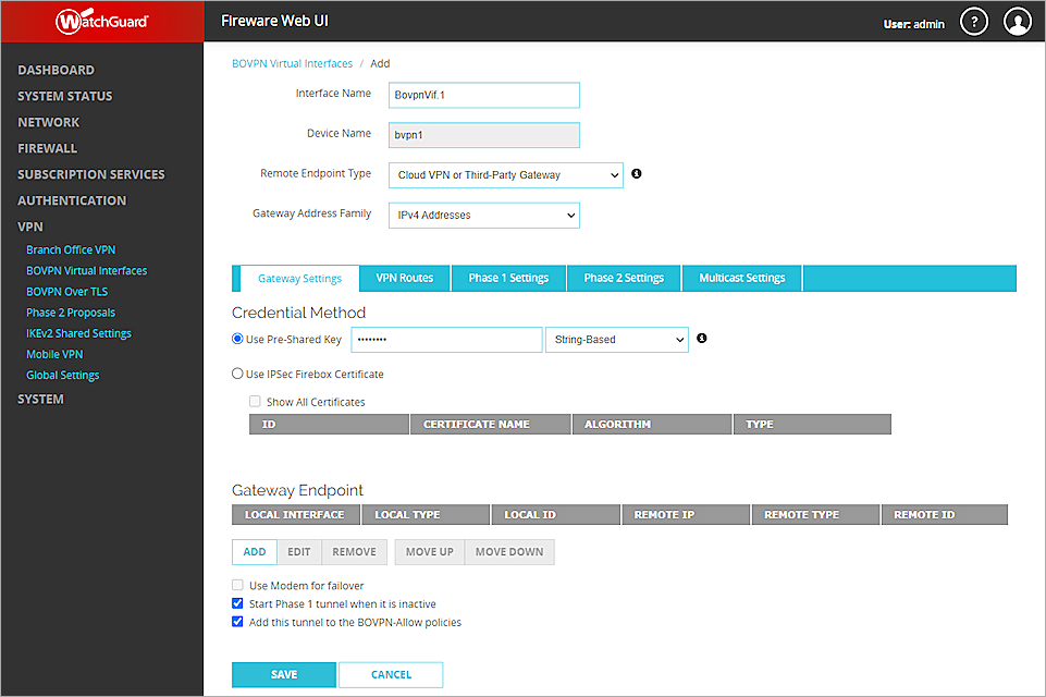
- In the Gateway Endpoint section, click Add.
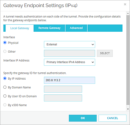
The Gateway Endpoint Settings dialog box opens. - From the External Interface drop-down list, select External.
- From the Interface IP Address drop-down list, select Primary Interface IPv4 Address.
The Primary Interface IP Address is the primary IP address you configured on the selected external interface. - Select By IP Address.
- In adjacent text box, type the primary IP address of the External Firebox interface.
- Select the Remote Gateway tab.
- Select Static IP Address.
- In the adjacent text box, type the IP address of your Cisco ISR WAN connection.
- Select By IP Address.
- In the adjacent text box, type the IP address of your Cisco ISR WAN connection.
- Keep the default settings for all other options.
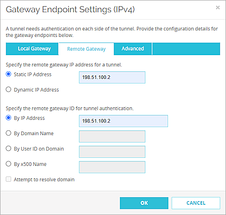
- Click OK.

Next, configure the VPN Route settings.
- Select the VPN Routes tab.
- Click Add.
- From the Choose Type drop-down list, select Network IPv4.
- In the Route To text box, type the Network IP address of a route that will use this virtual interface.
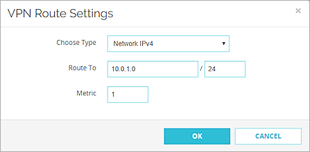
- Click OK.
Next, configure the Phase 1 and Phase 2 settings:
- Select the Phase 1 Settings tab.
- From the Version drop-down list, select IKEv2.
- Keep all other Phase 1 settings as default values.

- Keep the default values for Phase 2 settings.
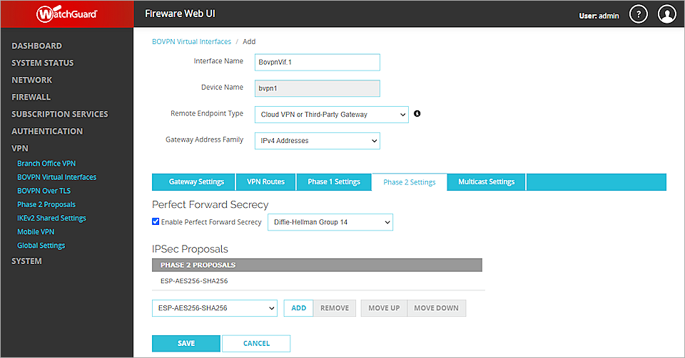
- Click Save.
For more information about BOVPN virtual interfaces on the Firebox, see BOVPN Virtual Interfaces
Configure the Cisco ISR
To configure the Cisco ISR, from the Cisco CLI:
- Create an IKE proposal to establish Phase 1 of the VPN tunnel:
Router>enable
Router#config t
Router(config)#
Router(config)#crypto ikev2 proposal wg-proposal
The IKEv2 proposal must be one of these two options:
- Option 1 — Encryption algorithm other than AES-GCM, an integrity algorithm, and a Diffie-Hellman group. In our example, we use AES-CBC-256, SHA256, and Diffie-Hellman group 14.
- Option 2 — AES-GCM encryption algorithm, a PRF algorithm, and a Diffie-Hellman group.
- Add the proposal that you created to an IKEv2 policy:
- Create a keyring and specify the VPN pre-shared key:
- Associate Phase 1 settings with a Phase 1 profile:
Router(config-ikev2-proposal)#encryption aes-cbc-256
Router(config-ikev2-proposal)#integrity sha256
Router(config-ikev2-proposal)#group 14
Router(config-ikev2-proposal)#exit
Router(config)#crypto ikev2 policy wg-policy
The IKEv2 policy must have at least one complete proposal attached.
Router(config-ikev2-policy)#proposal wg-proposal
Router(config-ikev2-policy)#exit
Router(config)#crypto ikev2 keyring wg-key
Router(config-ikev2-keyring)#peer WG
Router(config-ikev2-keyring-peer)#address 203.0.113.2
Router(config-ikev2-keyring-peer)#pre-shared-key 11111111
You must specify the same pre-shared key that you specified in the BOVPN configuration on the Firebox.
Router(config-ikev2-keyring-peer)#exit
Router(config-ikev2-keyring)#exit
Router(config)#
Router(config)#crypto ikev2 profile profile-ph1-wg
An IKEv2 profile must have:
- A local and a remote authentication method
- A match identity, match certificate, or match any statement
- Create a transform set for Phase 2 (IPSec):
- Associate Phase 2 settings with a Phase 2 profile and link that to the Phase 1 profile:
- Create a tunnel:
- Set the VPN tunnel router:
Router(config-ikev2-profile)#match identity remote address 203.0.113.2 255.255.255.255
Router(config-ikev2-profile)#authentication remote pre-share
Router(config-ikev2-profile)#authentication local pre-share
Router(config-ikev2-profile)#keyring local wg-key
Router(config-ikev2-profile)#match address local interface GigabitEthernet0/0
Router(config-ikev2-profile)#exit
Router(config)#crypto ipsec transform-set wg-set esp-aes 256 esp-sha256-hmac
Router(cfg-crypto-trans)#mode tunnel
Router(cfg-crypto-trans)#exit
Router(config)#
Router(config)#crypto ipsec profile profile-ph2-wg
Router(ipsec-profile)#set transform-set wg-set
Router(ipsec-profile)#set ikev2-profile profile-ph1-wg
Router(ipsec-profile)#exit
Router(config)#int tunnel 1
Router(config-if)#ip address 169.254.0.1 255.255.255.0
Router(config-if)#ip tcp adjust-mss 1350
Router(config-if)#tunnel source GigabitEthernet0/0
Router(config-if)#tunnel mode ipsec ipv4
Router(config-if)#tunnel destination 203.0.113.2
Router(config-if)#tunnel protection ipsec profile profile-ph2-wg
Router(config-if)#exit
Router(config)#
Router(config)#ip route 192.168.13.0 255.255.255.0 tunnel 1
Router(config)#exit
For more information about Cisco ISR VPN configuration and supported IKE ciphers, see the Cisco ISR 1921 Configuration Guides.
Test the Integration
To test the integration, from Fireware Web UI:
- Select System Status > VPN Statistics.
- Select the Branch Office VPN tab and verify the VPN is established.
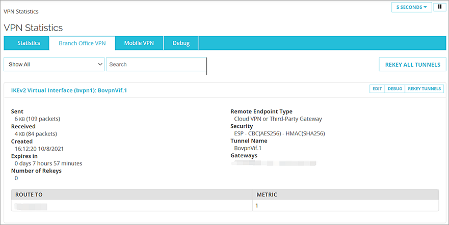
- Verify that Host1 (behind the Firebox) and Host2 (behind the Cisco ISR) can ping each other.