WatchGuard provides integration instructions to help our customers configure WatchGuard products to work with products created by other organizations. If you need more information or technical support about how to configure a third-party product, refer to the documentation and support resources for that product.
This integration guide describes how to configure a Branch Office VPN tunnel between a WatchGuard Firebox and a Cisco Integrated Services Router (ISR).
Contents
Integration Summary
The hardware and software used in this guide include:
- WatchGuard Firebox
- Fireware v12.10 or higher
- Cisco ISR C921-4P
- Version 15.9.3M8
Topology
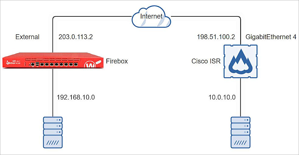
This diagram shows the topology for a BOVPN connection between a Firebox and a Cisco ISR.
Configure the Firebox
To configure a Branch Office VPN connection on the Firebox, from Fireware Web UI:
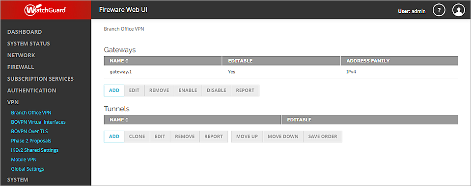
- Select VPN > Branch Office VPN.
The Branch Office VPN configuration page opens. - In the Gateways section, click Add.
- In the Gateway Name text box, type a name to identify this Branch Office VPN Gateway.
- From the Address Family drop-down list, select IPV4 Addresses.
- In the Credential Method section, select Use Pre-Shared Key.
- In the adjacent text box, type the pre-shared key (eg.11111111 in this guide).
- In the adjacent drop-down list, select String-Based.
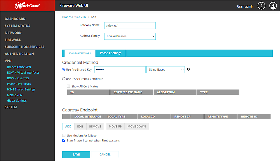
- In the Gateway Endpoint section, click Add.
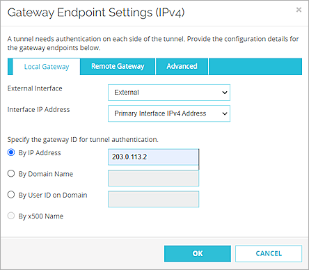
The Gateway Endpoint Settings dialog box opens. - From the External Interface drop-down list, select External.
- From the Interface IP Address drop-down list, select Primary Interface IPv4 Address.
The Primary Interface IP Address is the primary IP address you configured on the selected external interface. - Select By IP Address.
- In adjacent text box, type the primary IP address of the External Firebox interface.
- Select the Remote Gateway tab.
- Select Static IP Address.
- In the adjacent text box, type the IP address of your Cisco ISR WAN connection.
- Select By IP Address.
- In the adjacent text box, type the IP address of your Cisco ISR WAN connection.
- Leave the default value for all other settings.
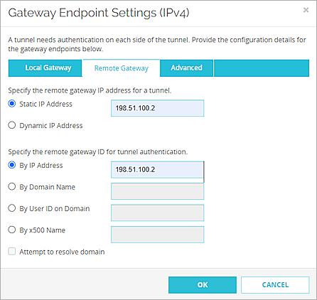
- Click OK.
- In the Gateway Endpoint section, select the Start Phase 1 tunnel when Firebox starts check box.

- Select the Phase 1 Settings tab.
- From the Version drop-down list, select IKEv2.
- Leave the default value for all other Phase 1 settings.
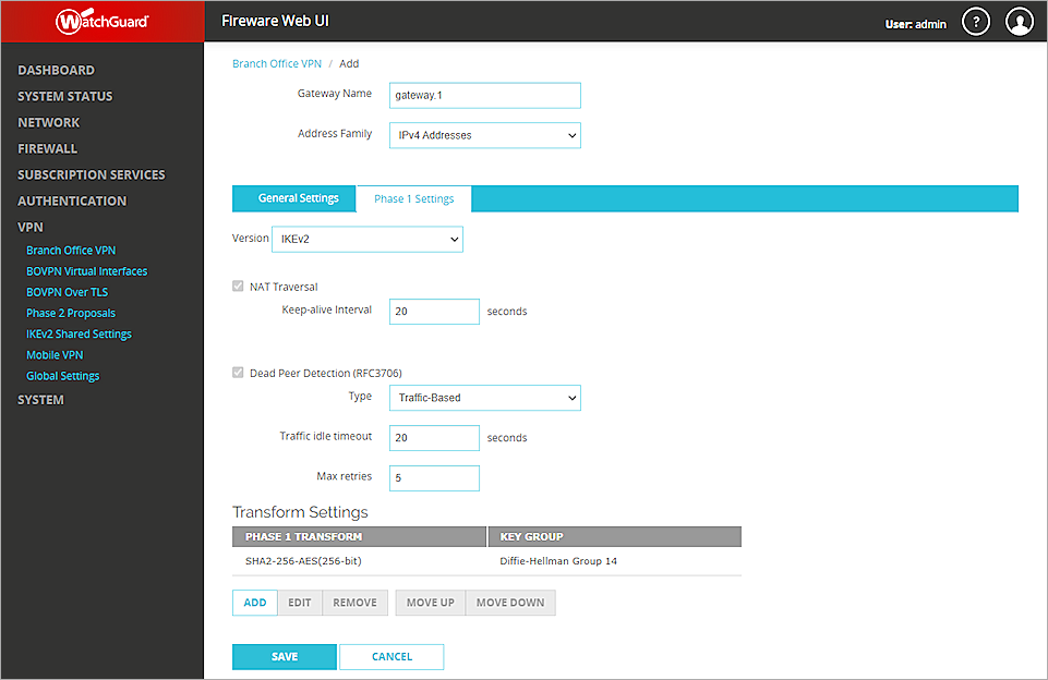
- Click Save.
- In the Tunnels section, click Add.
- From the Gateway drop-down list, select the gateway that you configured.
- In the Addresses section, click Add.

- In the Local IP section, from the Choose Type drop-down list, select Network IPv4.
- In the Network IP text box, type the local IP segment. This is the local network protected by the Firebox.
- In the Remote IP section, from the Choose Type drop-down list, select Network IPv4.
- In the Network IP text box, type the remote IP segment. This is the local network protected by the Cisco ISR.
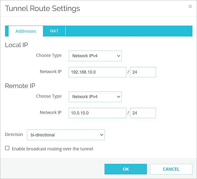
- Click OK.
- Leave the default value for all other Phase 2 settings.

- Click Save.
Configure the Cisco ISR
To configure the Cisco ISR, from the Cisco CLI:
- Define the keyring and specify your VPN pre-shared key:
- Define the IKEv2 proposal:
- Option 1 — Encryption algorithm other than AES-GCM, an integrity algorithm, and a Diffie-Hellman group. In our example, we use AES-CBC-256, SHA256, and Diffie-Hellman group 14.
- Option 2 — AES-GCM encryption algorithm, a PRF algorithm, and a Diffie-Hellman group.
- Define the IKEv2 policy:
- Define the crypto ACL:
- Define the transform set:
- Define the IKEv2 profile:
- A local and a remote authentication method
- A match identity, match certificate, or match any statement
- Define the crypto map:
- Activate the crypto map by applying the interface:
Router>enable
Router#config t
Router(config)#
Router(config)#crypto ikev2 keyring wg-key
Router(config-ikev2-keyring)#peer WG
Router(config-ikev2-keyring-peer)#address 203.0.113.2
Router(config-ikev2-keyring-peer)#pre-shared-key 11111111
You must specify the same pre-shared key that you specified in the BOVPN configuration on the Firebox.
Router(config-ikev2-keyring-peer)#exit
Router(config-ikev2-keyring)#exit
Router(config)#
Router(config)#crypto ikev2 proposal wg-proposal
The IKEv2 proposal must be one of these two options:
Router(config-ikev2-proposal)#encryption aes-cbc-256
Router(config-ikev2-proposal)#integrity sha256
Router(config-ikev2-proposal)#group 14
Router(config-ikev2-proposal)#exit
Router(config)#
Router(config)#crypto ikev2 policy wg-policy
The IKEv2 policy must have at least one complete proposal attached.
Router(config-ikev2-policy)#proposal wg-proposal
Router(config-ikev2-policy)#exit
Router(config)#
Router(config)#ip access-list extended SITE1-SITE2-CACL
Router(config-ext-nacl)#permit ip 10.0.10.0 0.0.0.255 192.168.10.0 0.0.0.255
Router(config-ext-nacl)#exit
Router(config)#
Router(config)#crypto ipsec transform-set wg-set esp-aes 256 esp-sha256-hmac
Router(cfg-crypto-trans)#exit
Router(config)#
Router(config)#crypto ikev2 profile wg-profile
An IKEv2 profile must have:
Router(config-ikev2-profile)#match identity remote address 203.0.113.2 255.255.255.255
Router(config-ikev2-profile)#authentication local pre-share
Router(config-ikev2-profile)#authentication remote pre-share
Router(config-ikev2-profile)#keyring local wg-key
Router(config-ikev2-profile)#exit
Router(config)#
Router(config)#crypto map wg-map 10 ipsec-isakmp
The new crypto map remains disabled until a peer and a valid access list are configured.
Router(config-crypto-map)#set peer 203.0.113.2
Router(config-crypto-map)#set pfs group14
Router(config-crypto-map)#set security-association lifetime seconds 3600
Router(config-crypto-map)#set transform-set wg-set
Router(config-crypto-map)#set ikev2-profile wg-profile
Router(config-crypto-map)#match address SITE1-SITE2-CACL
Router(config-crypto-map)#exit
Router(config)#
Router(config)#interface GigabitEthernet4
Router(config-if)#crypto map wg-map
Router(config-if)#exit
Router(config)#exit
Router#
For more information about the Cisco ISR VPN configuration and supported IKE ciphers, go to the Cisco ISR 1921 Configuration Guides.
Test the Integration
To test the integration, from Fireware Web UI:
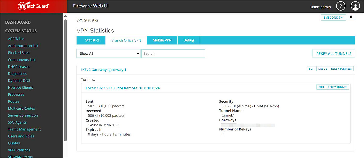
- Select System Status > VPN Statistics.
- Select the Branch Office VPN tab and verify the VPN is established.
- Verify that the Host behind the Firebox and the Host behind the Cisco ISR can ping each other.