Deployment Overview
WatchGuard provides integration instructions to help our customers configure WatchGuard products to work with products created by other organizations. If you need more information or technical support about how to configure a third-party product, see the documentation and support resources for that product.
This integration guide describes how to configure a Branch Office VPN (BOVPN) virtual interface connection between a WatchGuard Firebox and a Cisco Adaptive Security Appliance (ASA).
Integration Summary
The hardware and software used in this guide include:
- WatchGuard Firebox
- Fireware v12.7.1 or higher
- Cisco ASA 5506-X
- ASDM v7.15 (1) 150
- ASA v9.15 (1) 16
Topology
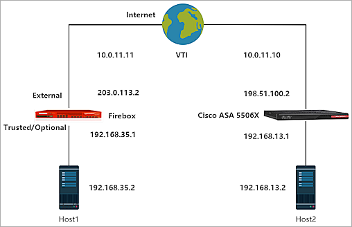
This diagram shows the topology for a BOVPN virtual interface connection between a Firebox and a Cisco ASA.
Configure the Firebox
On the Firebox, configure a BOVPN virtual interface connection:
- Log in to Fireware Web UI.
- Select VPN > BOVPN Virtual Interfaces.
The BOVPN Virtual Interfaces configuration page opens. - Click Add.
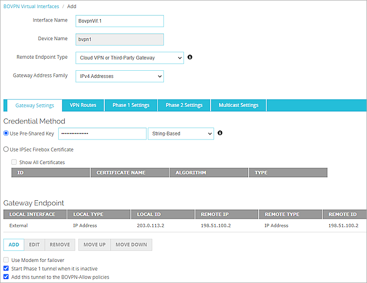
- In the Interface Name text box, type a name to identify this BOVPN virtual interface.
- From the Remote Endpoint Type drop-down list, select Cloud VPN or Third-Party Gateway.
- From the Gateway Address Family drop-down list, select IPv4 Addresses.
- In the Credential Method section, select Use Pre-Shared Key.
- In the adjacent text box, type the pre-shared key.
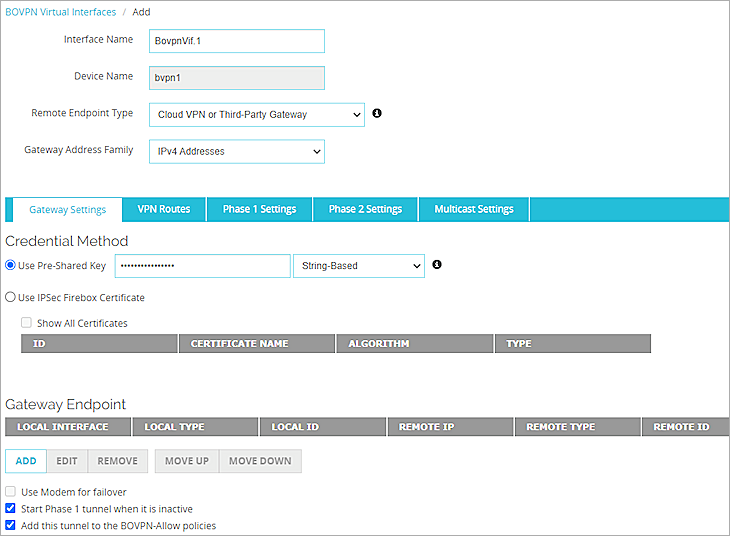
- In the Gateway Endpoint section, click Add.
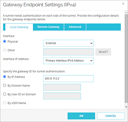
The Gateway Endpoint Settings dialog box opens. - From the Physical drop-down list, select External.
- From the Interface IP Address drop-down list, select Primary Interface IPv4 Address.
The Primary Interface IP Address is the primary IP address you configured on the selected external interface. - Select By IP Address.
- In the adjacent text box, type the primary IP address of the External Firebox interface.
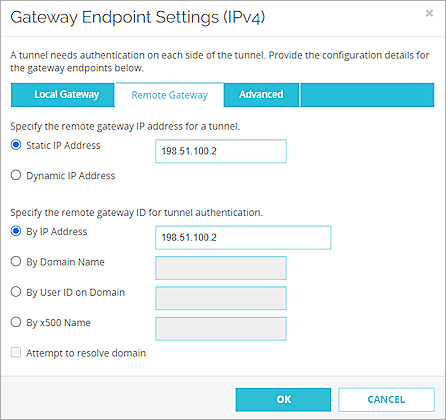
- Select the Remote Gateway tab.
- Select Static IP Address.
- In the adjacent text box, type the IP address of your Cisco ASA WAN connection.
- Select By IP Address.
- In the adjacent text box, type the IP address of your Cisco ASA WAN connection.
- Click OK.
- In the Gateway Endpoint section, select Start Phase 1 tunnel when it is inactive.
- Select Add this tunnel to the BOVPN-Allow policies.
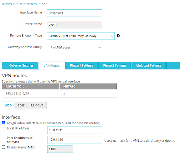
- Select the VPN Routes tab.
- Click Add.
- From the Choose Type drop-down list, select Network IPv4.
- In the Route To text box, type the Network IP address of a route that will use this virtual interface.
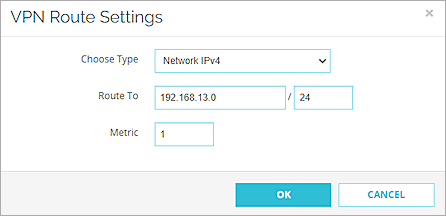
- Click OK.
- Select the Assign virtual interface IP addresses (required for dynamic routing) check box.
- In the Local IP address and Peer IP address or netmask text boxes, type the virtual interface IP addresses.
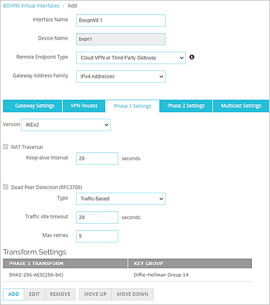
- Select the Phase 1 Settings tab.
- From the Version drop-down list, select IKEv2.
- Keep all other Phase 1 settings as the default values.
- Keep all other Phase 2 settings as the default values.
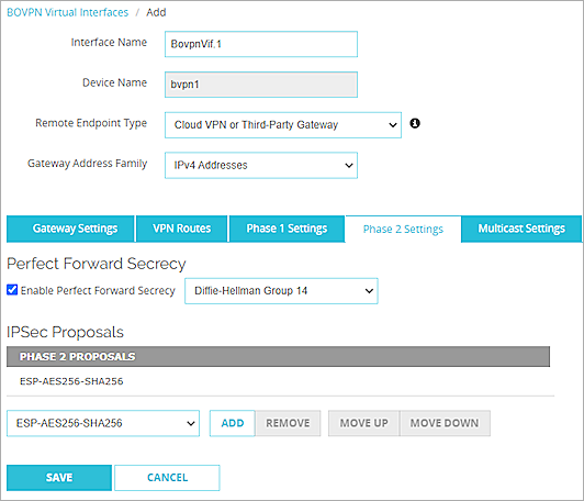
- Click Save.
For more information about BOVPN virtual interface configuration on the Firebox, see BOVPN Virtual Interfaces
Configure the Cisco ASA
In our example, we configure a Cisco ASA 5506-X.
To configure the basic settings:
- Log in to the ASA 5506-X with Cisco Adaptive Security Device Manager (ASDM). The default IP address is 192.168.1.1.
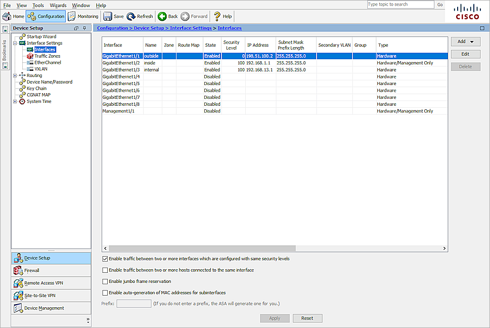
- Configure the ASA 5506-X interfaces. For information about how to configure interfaces, see the Cisco ASA 5506-X documentation.
- Select the Enable traffic between two or more interfaces which are configured with same security levels check box.
- Click Apply.
Next, configure the IPSec VPN settings:
- Click Configuration.
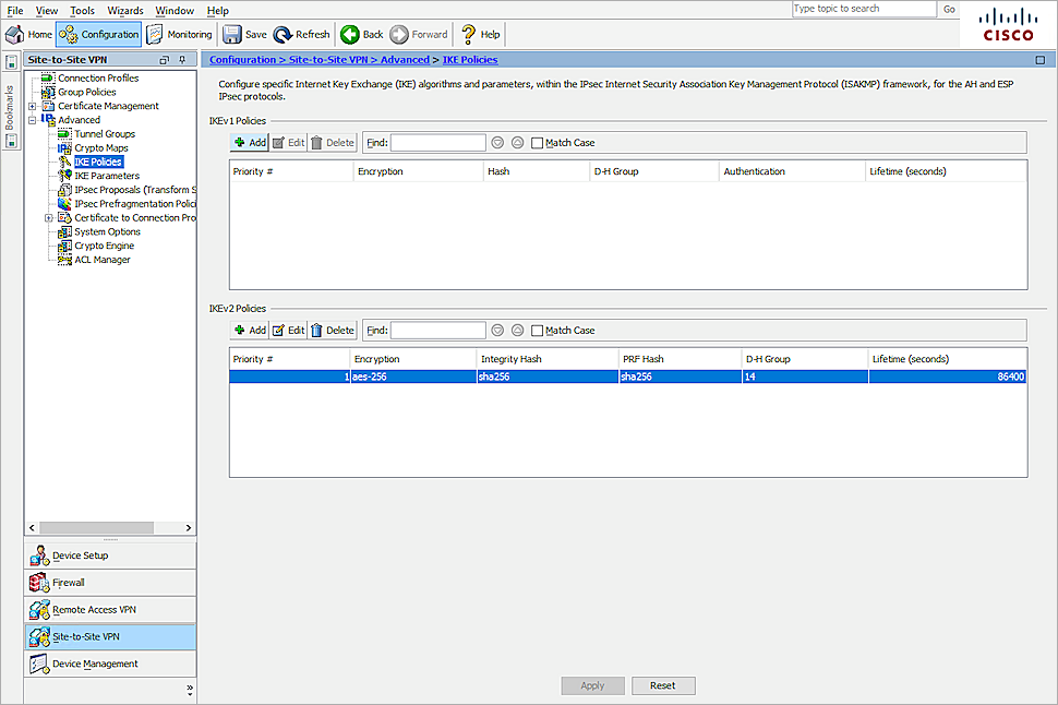
- Select Site-to-Site VPN > Advanced > IKE policies.
- In the IKEv2 Policies section, click Add.
- In the Priority text box, type 1.
- From the D-H Group drop-down list, select 14.
- From the Encryption drop-down list, select aes-256.
- From the Integrity Hash drop-down list, select sha256.
- From the Pseudo Random Function (PRF) Hash drop-down list, select sha256.
- Keep the default value for all other settings.
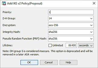
- Click OK.
- Click Apply.
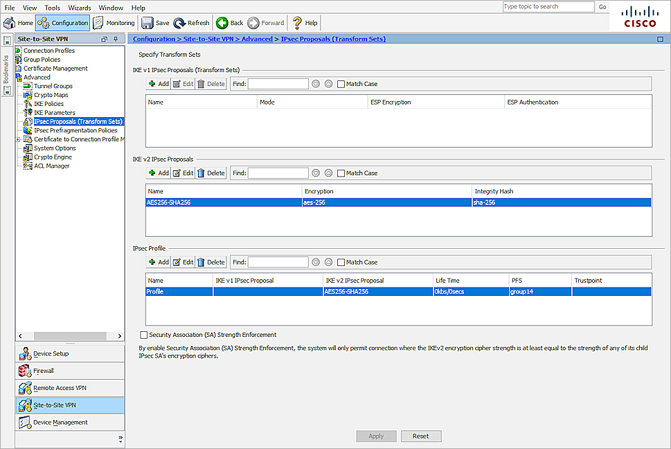
- Select Site-to-Site VPN > Advanced > IPsec Proposals (Transform Sets).
- In the IKE v2 IPsec Proposals section, click Add.
- In the Name text box, type an object name. In our example, we specify the name AES256-SHA256.
- From the Encryption drop-down list, select aes-256.
- From the Integrity Hash drop-down list, select sha-256.
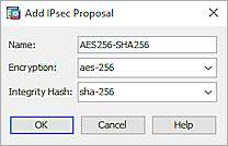
- Click OK.
- In the IPsec Profile section, click Add.
- In the Name text box, type the IPSec profile name. In our example, we specify the name Profile.
- In the IKE v2 IPsec Proposal text box, type the proposal.
- Select PFS Settings and select group14.
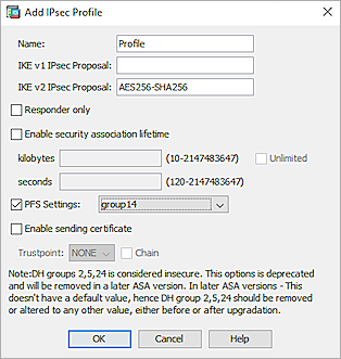
- Click OK.
- Click Apply.
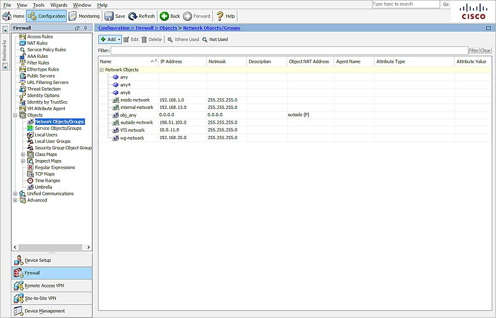
- Select Configuration > Firewall > Objects > Network Objects/Groups.
- Click Add > Network Object.
- In the Name text box, type the object name. In our example, we specify the name VTI-network.
- From the Type drop-down list, select Network.
- For IP Version, select IPv4.
- In the IP Address text box, type the IP address. In our example, we specify the IP address 10.0.11.0.
- In the Netmask text box, type the netmask. In our example, we specify the netmask 255.255.255.0.
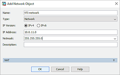
- Click OK.
- Repeat Steps 25–31 to create other network objects.
- Click Apply.
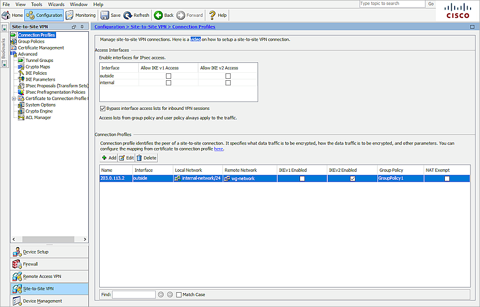
- Select Configuration > Site-to-Site VPN > Connection Profiles.
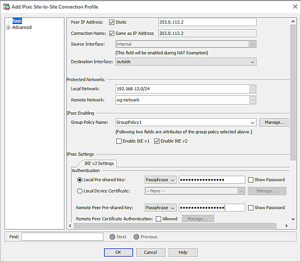
- In the Connection Profiles section, click Add.
- In the Peer IP Address text box, type the peer IP address.
- From the Interface drop-down list, select outside.
- From the Local Network list, select internal-network/24.
- From the Remote Network list, select wg-network.
- In the IPsec Enabling section, click Manage.
- Click Add.
- In the Name text box, type the name. In our example, we specify the name GroupPolicy1.
- In the Tunneling Protocols section, clear the Inherit check box and select IPsec IKEv2.
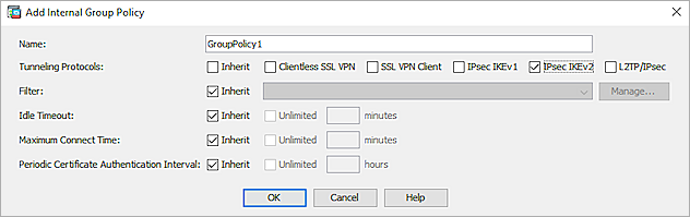
- Click OK > OK.
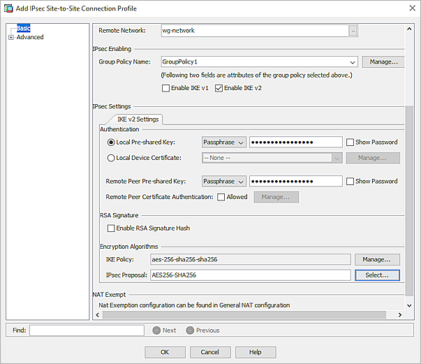
- Select Local Pre-shared Key.
- In the adjacent text box, type the pre-shared key.
- In the Remote Peer Pre-shared Key text box, type the pre-shared key.
- For the IKE Policy setting, keep the default value.
- From the IPsec Proposal list, select AES256-SHA256.
- For the Advanced settings, select Advanced > Crypto Map Entry.
- For Perfect Forward Secrecy, select Enable.
- From the Diffie-Hellman Group drop-down list, select group14.
- Keep all other settings as the default values.

- Click OK.
- Click Apply.
Next, configure the VTI interface settings:
- Click Configuration.
- Select Device Setup > Interface Settings > Interfaces.
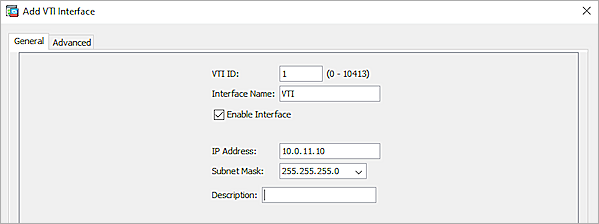
- Click Add > VTI Interface.
- In the VTI ID text box, type the VTI ID.
- In the Interface Name text box, type the interface name.
- Select Enable Interface.
- In the IP Address text box, type the IP address.
- In the Subnet Mask drop-down list, select 255.255.255.0.
- Select the Advanced tab.
- In the Destination IP text box, type the destination IP address.
- From the Source Interface drop-down list, select outside.
- From the Tunnel Protection with Ipsec Profile drop-down list, select Profile.
- Select the Enable Tunnel Mode IPv4 Ipsec check box.
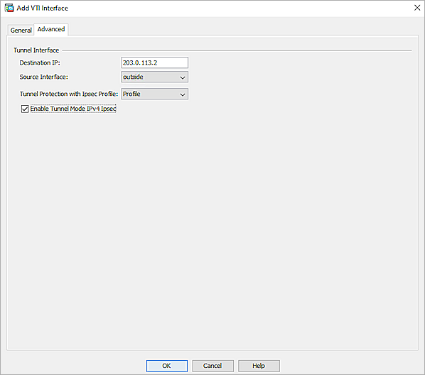
- Click OK.
- Click Apply.
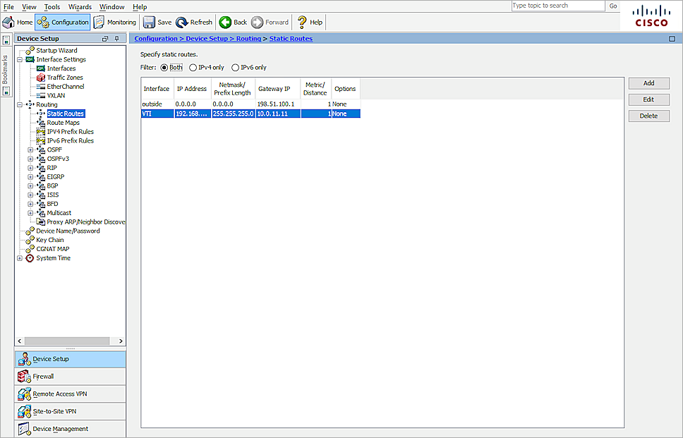
Finally, configure the routing settings:
- Select Configuration > Device Setup > Routing > Static Routes.
- Click Add.
- Select IPv4.
- From the Interface drop-down list, select VTI.
- From the Network drop-down list, select wg-network.
- In the Gateway IP text box, type the gateway IP address.
- For all other settings, keep the default values.
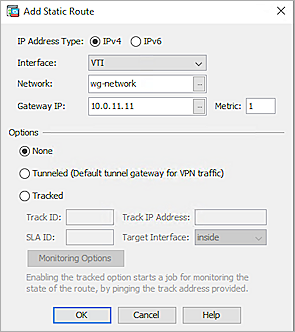
- Click OK.
- Click Apply.
Test the Integration
To test the integration, from Fireware Web UI:
- Select System Status > VPN Statistics.
- Select the Branch Office VPN tab and verify the VPN is established.
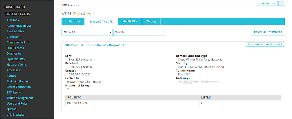
- Verify that Host1 (behind the Firebox) and Host2 (behind the Cisco ASA) can ping each other.