WatchGuard provides integration instructions to help our customers configure WatchGuard products to work with products created by other organizations. If you need more information or technical support about how to configure a third-party product, refer to the documentation and support resources for that product.
This integration guide describes how to configure a Branch Office VPN (BOVPN) tunnel between a WatchGuard Firebox and a Cisco Adaptive Security Appliance (ASA).
Contents
Integration Summary
The hardware and software used in this guide include:
- WatchGuard Firebox
- Fireware v12.10 or higher
- Cisco ASA 5506-X
- ASDM 7.20(1)
- ASA 9.16(4)19
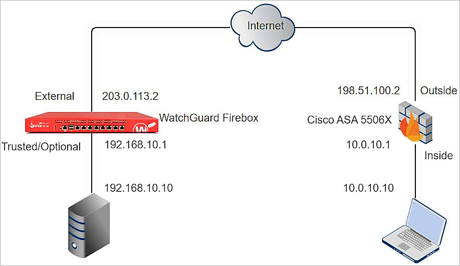
Topology
This diagram shows the topology for a BOVPN connection between a Firebox and a Cisco ASA.
Configure the Firebox
To configure a BOVPN connection on the Firebox, from Fireware Web UI:
- Select VPN > Branch Office VPN.
The Branch Office VPN configuration page opens. - In the Gateways section, click Add.
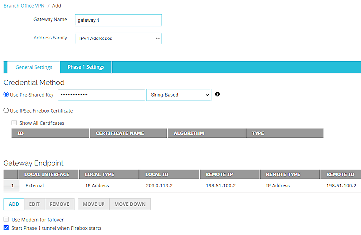
- In the Gateway Name text box, type a name to identify this Branch Office VPN gateway.
- From the Address Family drop-down list, select IPv4 Addresses.
- In the Credential Method section, select Use Pre-Shared Key.
- In the adjacent text box, type the pre-shared key.
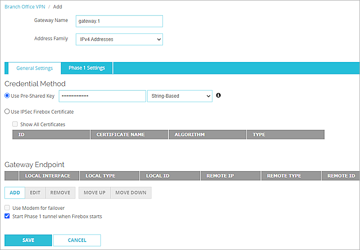
- In the Gateway Endpoint section, click Add.
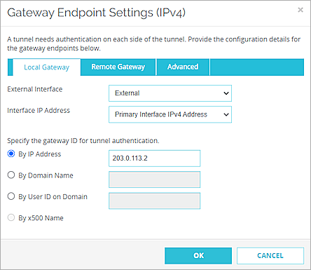
The Gateway Endpoint Settings dialog box opens. - From the External Interface drop-down list, select External.
- From the Interface IP Address drop-down list, select Primary Interface IPv4 Address.
The Primary Interface IP Address is the primary IP address you configured on the selected external interface. - Select By IP Address.
- In the adjacent text box, type the primary IP address of the External Firebox interface.
- Select the Remote Gateway tab.
- Select Static IP Address.
- In the adjacent text box, type the IP address of your Cisco ASA WAN connection.
- Select By IP Address.
- In the adjacent text box, type the IP address of your Cisco ASA WAN connection.
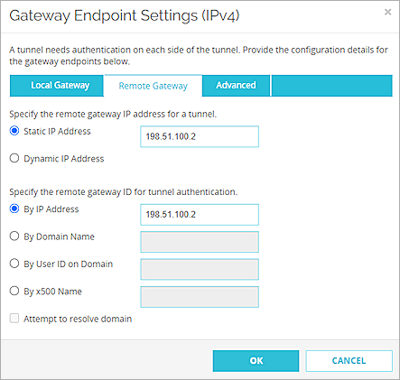
- Click OK.
- In the Gateway Endpoint section, select the Start Phase 1 tunnel when Firebox starts check box.
- Select the Phase 1 Settings tab.
- From the Version drop-down list, select IKEv2.
- Keep all other Phase 1 settings as the default values.
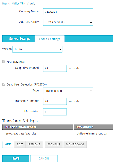
- Click Save.
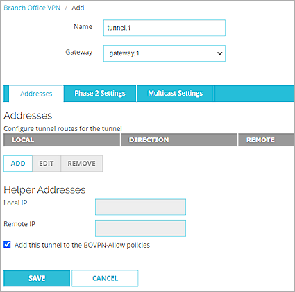
- In the Tunnels section, click Add.
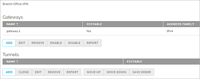
- From the Gateway drop-down list, select the gateway that you configured.
- In the Addresses section, click Add.
- In the Local IP section, from the Choose Type drop-down list, select Network IPv4.
- In the Network IP text box, type the local IP segment. This is the local network protected by the Firebox.
- In the Remote IP section, from the Choose Type drop-down list, select Network IPv4.
- In the Network IP text box, type the remote IP segment. This is the local network protected by the Cisco ASA.
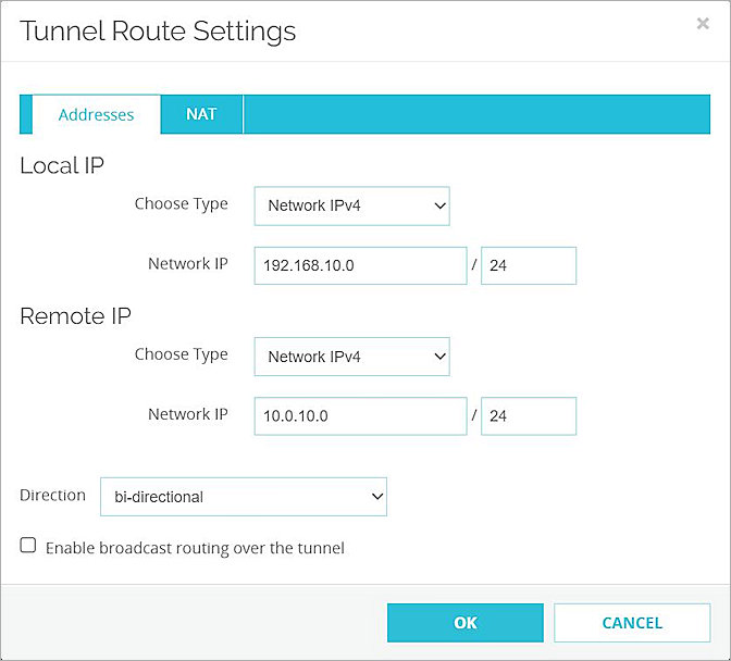
- Click OK.
- Keep Phase 2 Settings as the default values.
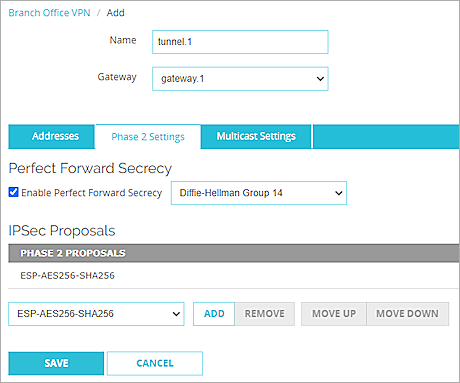
- Click Save.
Configure the Cisco ASA
In our example, we configure a Cisco ASA 5506-X.
To configure the ASA 5506-X basic settings:
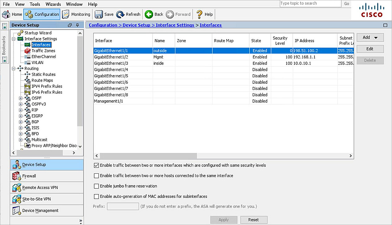
- Log in to the ASA 5506-X with ASDM. The default IP address is 192.168.1.1.
- Configure the ASA 5506-X interfaces. For information about how to configure interfaces, refer to the Cisco ASA 5506-X documentation.
- Select the Enable traffic between two or more interfaces which are configured with same security levels check box.
- Click Apply.
To configure the IPSec VPN settings:
- Click Configuration.
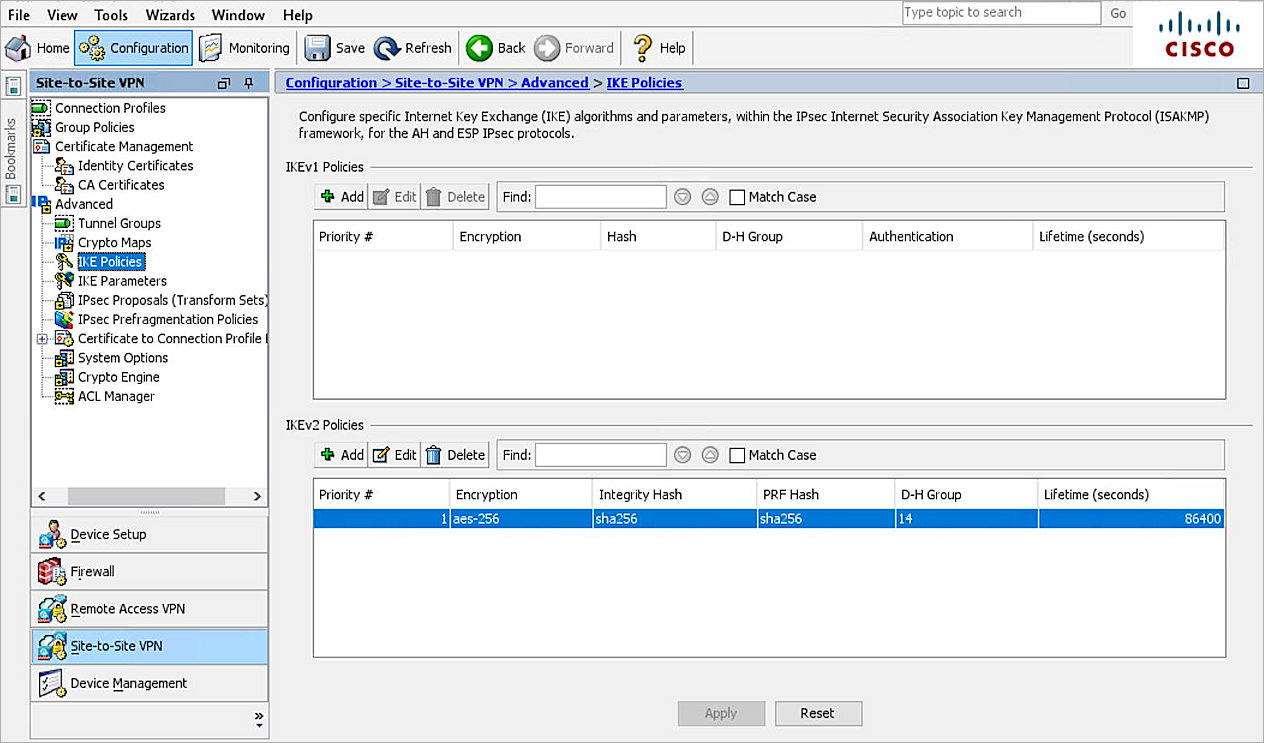
- Select Site-to-Site VPN > Advanced > IKE policies.
- In the IKEv2 Policies section, click Add.
- In the Priority text box, type 1.
- From the D-H Group drop-down list, select 14.
- From the Encryption drop-down list, select aes-256.
- From the Integrity Hash drop-down list, select sha256.
- From the Pseudo Random Function (PRF) Hash drop-down list, select sha256.
- Leave the default value for all other settings.
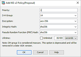
- Click OK.
- Click Apply.
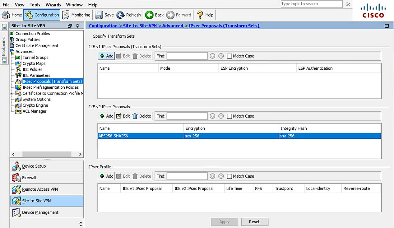
- Select Configuration > Site-to-Site VPN > Advanced > IPsec Proposals (Transform Sets).
- In the IKEv2 IPsec Proposals section, click Add.
- In the Name text box, type an object name. In our example, we specify the name AES256-SHA256.
- From the Encryption drop-down list, select aes-256.
- From the Integrity Hash drop-down list, select sha-256.
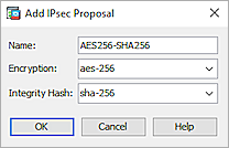
- Click OK.
- Click Apply.
- From the navigation menu, select Configuration > Firewall > Objects > Network Objects/Groups.
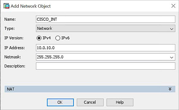
- Click Add > Network Object.
- In the Name text box, type the object name. In our example, we specify the name WG_INT. Which is used for the network protected by the WatchGuard Firebox.
- From the Type drop-down list, select Network.
- From the IP Version check box, check IPv4.
- In the IP Address text box, type the IP address. For this example, we use IP address 192.168.10.0.
- In the Netmask text box, type the netmask. For this example, we use netmask 255.255.255.0.
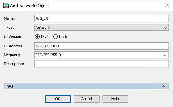
- Click OK.
- Repeat Steps 20–26 to create another network object. For this example, we name the network object CISCO_INT. This is used for the network protected by the Cisco ASA.
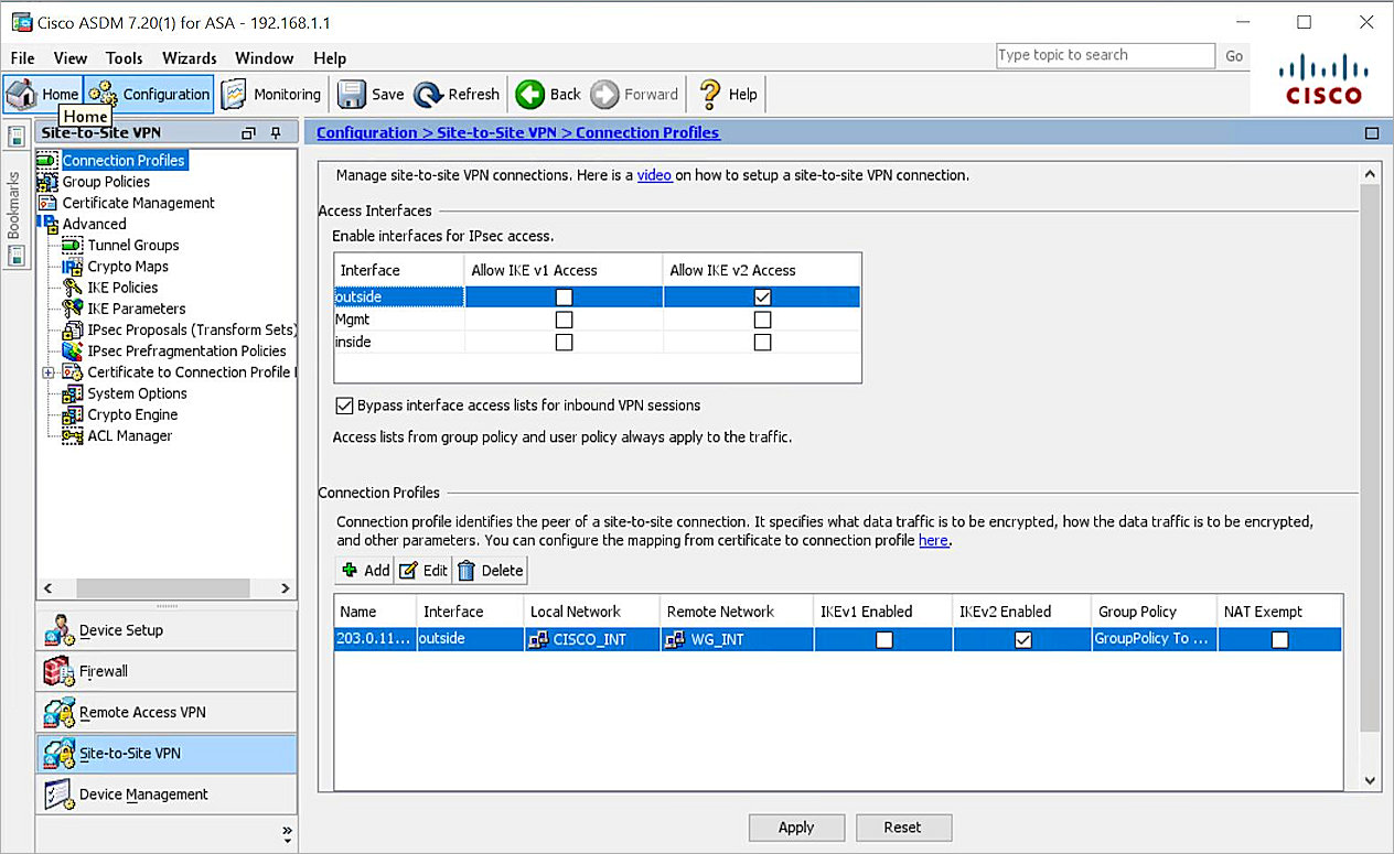
- Select Configuration > Site-to-Site VPN > Connection Profiles.
- In the Connection Profiles section, click Add.
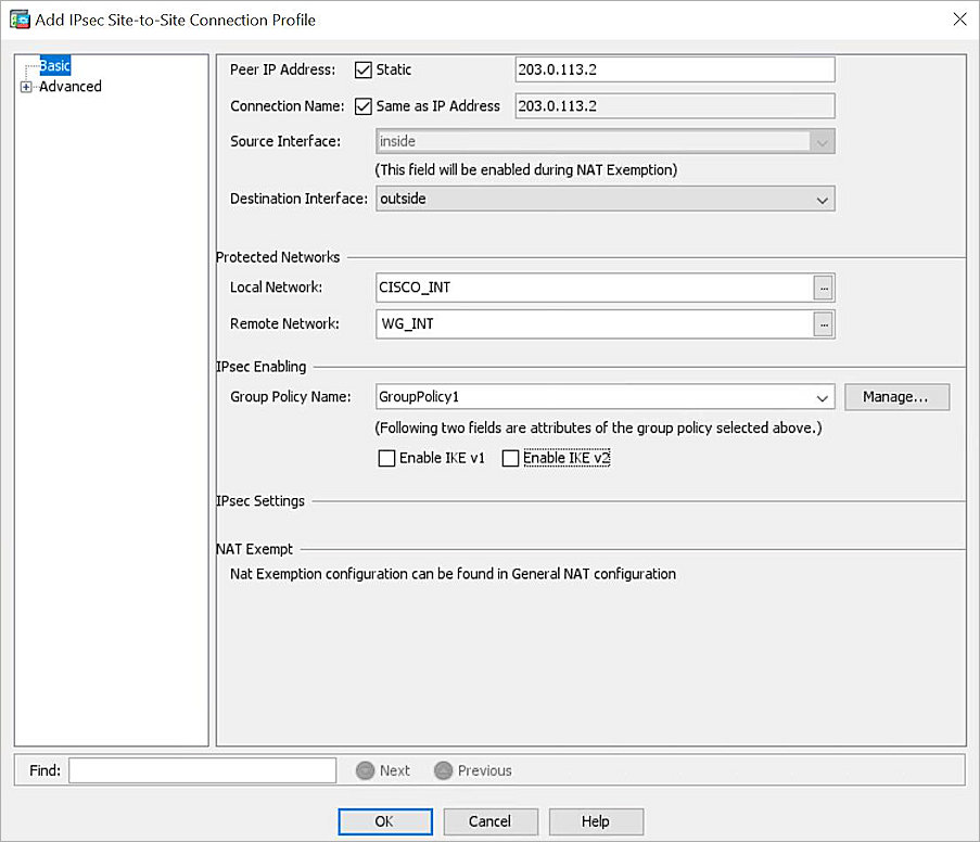
- In the Peer IP Address text box, type the peer IP address.
- From the Source Interface drop-down list, select inside.
- From the Destination Interface drop-down list, select outside.
- From the Local Network list, select CISCO_INT.
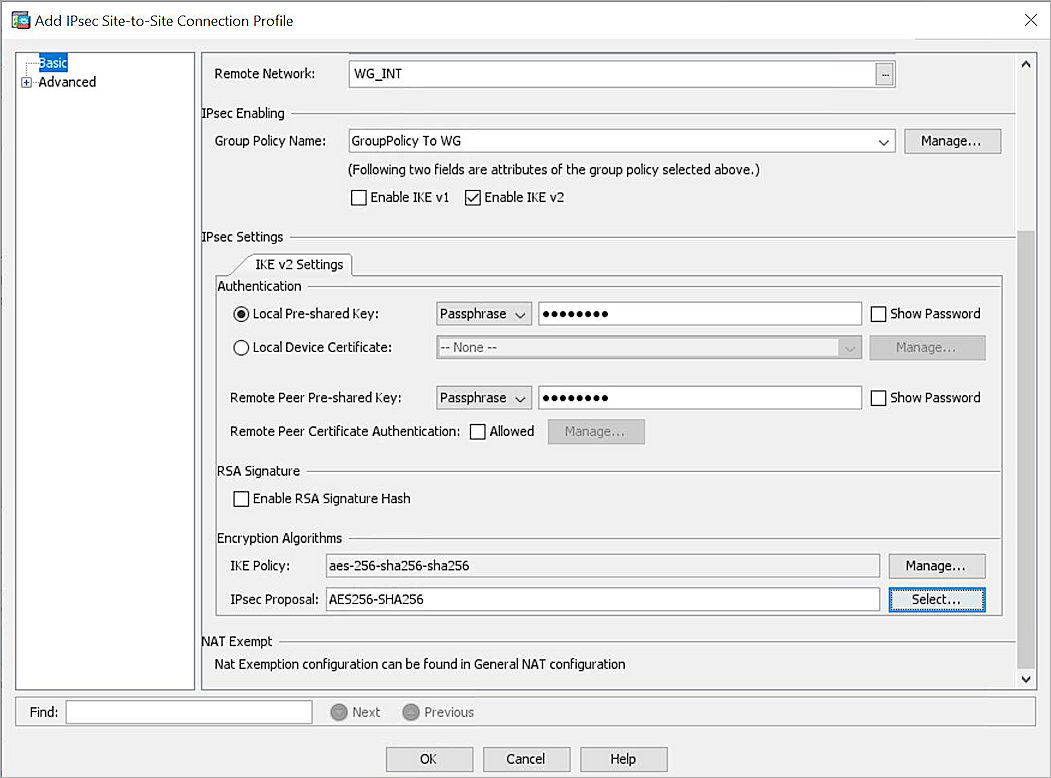
- From the Remote Network list, select WG_INT.
- In the IPsec Enabling section, click Manage.
- Click Add.
- In the Name text box, type the name. For this example, we use GroupPolicy To WG.
- In the Tunneling Protocols section, clear the Inherit check box and select IPsec IKEv2.
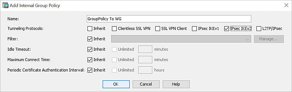
- Click OK > OK.
- Select Local Pre-shared Key.
- In the adjacent text box, type the pre-shared key.
- In the Remote Peer Pre-shared Key text box, type the pre-shared key.
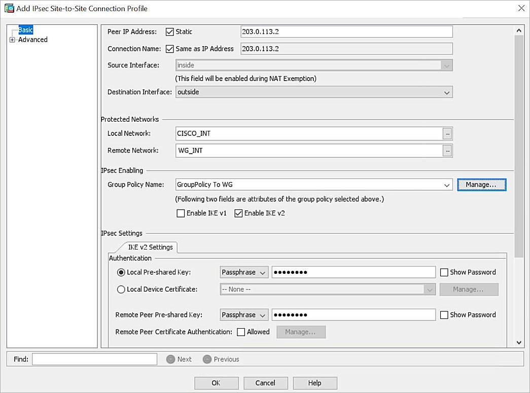
- For the IKE Policy setting, keep the default value.
- From the IPsec Proposal list, select AES256-SHA256.
- For the Advanced settings, select Advanced > Crypto Map Entry.
- In the Perfect Forward Secrecy section, select Enable.
- From the Diffie-Hellman Group drop-down list, select group14.
- Leave the default value for all other settings.
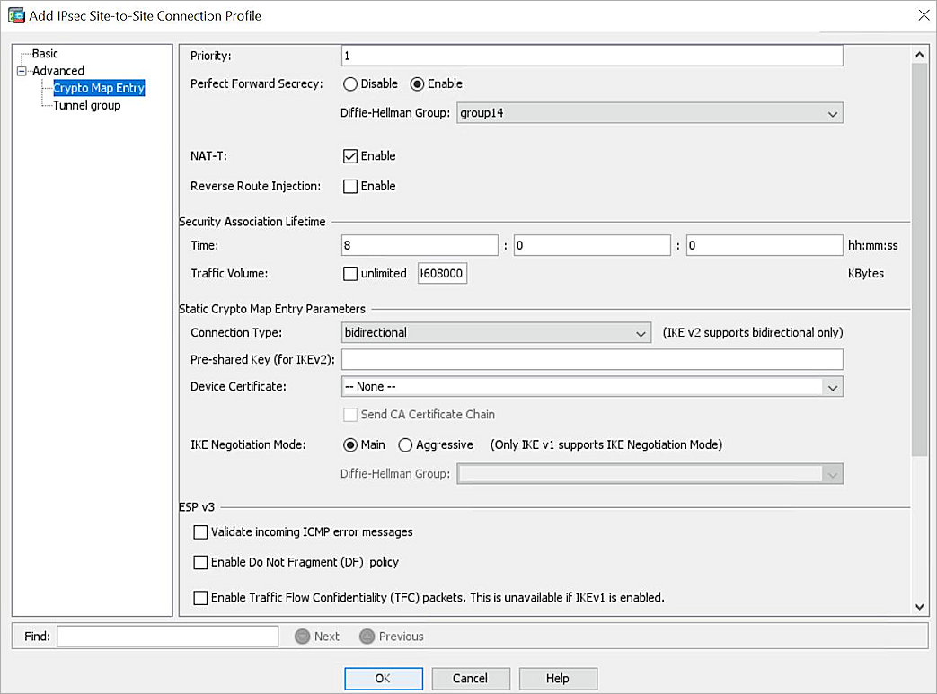
- Click OK.
- In the Enable interfaces for IPsec access section, select the outside interface and select Allow IKE v2 Access.
- Click Apply.
- From the navigation menu, select Configuration > Firewall > NAT Rules.
- Click Add.
- In the Match Criteria: Original Packet section, from the Source Interface drop-down list, select inside.
- From the Source Address drop-down list, select CISCO_INT.
- From the Destination Interface drop-down list, select outside.
- From the Destination Address drop-down list, select WG_INT.
- Under Options, Select the Disable Proxy ARP on egress interface check box.
- Select the Lookup route table to locate egress interface check box.
- Leave the default value for all other settings.

- Click OK.
- Click Apply.
Test the Integration
To test the integration, from Fireware Web UI:
- Select System Status > VPN Statistics.
- Select the Branch Office VPN tab and verify the VPN is established.
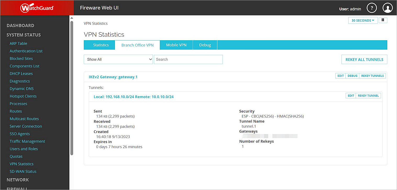
- Verify that the Host behind the Firebox and the Host behind the Cisco ASA can ping each other.