
Related Topics
BOVPN Virtual Interface Examples
When you configure a branch office VPN as a virtual interface, the Firebox sends a packet through the tunnel based on the outgoing interface for the packet. The BOVPN virtual interface is in the routing table, and the decision about whether to send traffic through the VPN tunnel is affected by static and dynamic routes and by policy-based routing. This provides flexibility in how you can configure the Firebox to use a BOVPN tunnel.
Because a BOVPN virtual interface is considered another interface in the configuration, it provides many flexible configuration and routing options. This topic includes three configuration options that show some of the methods to configure a Firebox to use a BOVPN virtual interface to achieve different objectives.
Metric-Based VPN Failover and Failback
Objective
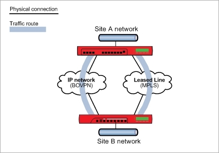
For two sites that are connected with an MPLS link, enable traffic to automatically failover and failback to a secondary branch office VPN connection over an IP network.
Configuration Summary
- Configure the external interfaces for the primary connection between the two sites over the MPLS network. The primary connection must use dynamic routing, or must be configured as a BOVPN virtual interface. This is required so the primary route either gets a higher metric or is removed from the routing table when the primary connection is not available.
- Configure a BOVPN virtual interface for the secondary link between the two sites.
- Add a BOVPN virtual interface static route and set a high metric (for example, 200) for the route.
For a detailed configuration example, see BOVPN Virtual Interface with Metric-Based Failover.
How it works
With this configuration, there are two routes between the two sites:
- A route over the MPLS network
- Another static route through the BOVPN virtual interface
When two routes are available, the final decision about which path a packet takes is based on which route has higher priority (a lower metric) than the other. Because the BOVPN virtual interface route has a high metric, the Firebox uses the primary route through the MPLS link when it is available. If the MPLS link is not available, the primary route is either removed from the routing table, or it is assigned a higher metric than the route for the secondary BOVPN virtual interface. The Firebox then uses the route for the secondary BOVPN virtual interface because it has the lowest route metric. When the MPLS route is available again, the Firebox automatically fails back to use that route because it has a lower metric.
You could use a similar configuration to enable automatic failover and failback between two BOVPN virtual interfaces. To enable automatic failover and failback, create two BOVPN virtual interfaces, with a static route for each, and set the metric for the preferred BOVPN route lower than the metric for the backup BOVPN route.
BOVPN Virtual Interface with Dynamic Routing
Objective
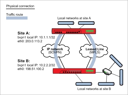
Enable two sites to dynamically exchange information about multiple local networks through a secure VPN tunnel. With this configuration, you do not have to manually add and maintain explicitly configured routes between all the private networks at each site.
To configure dynamic routing with BGP to Microsoft Azure, you must use Microsoft PowerShell. Dynamic routing with OSPF to a Microsoft Azure virtual network is not supported. For more information, see BOVPN Virtual Interface for Dynamic Routing to Microsoft Azure.
Dynamic routing with OSPF to an Amazon Web Services virtual network is not supported. For more information, see BOVPN Virtual Interface for Dynamic Routing to Amazon Web Services (AWS).
Configuration summary
- Configure a branch office VPN between the two sites as a BOVPN virtual interface. On the VPN Routes tab, configure virtual IP addresses. Make sure to select the Start Phase 1 tunnel when it is inactive check box.
- Enable dynamic routing between the two sites. In the dynamic routing configuration, use the virtual IP addresses as the peer network IP addresses.
- For OSPF, use the network command, and configure the peer virtual IP address with a /32 netmask.
For example, network <peer_virtual_ip>/32 area 0.0.0.0 - For BGP, use the neighbor command, and the peer virtual IP address
For example, neighbor <peer_virtual_ip> remote-as 65535
- For OSPF, use the network command, and configure the peer virtual IP address with a /32 netmask.
- Use dynamic routing commands to configure which local networks each device propagates routes for. To control the dynamic routes, you can use the Interface Cost for OSPF, or the Local Preference for BGP. For OSPF, the lower the Interface Cost, the more preferred the route. For BGP, the higher the Local Preference, the more preferred the route.
For detailed BOVPN configuration examples with dynamic routing, see:
- BOVPN Virtual Interface with Dynamic Routing
- BOVPN Virtual Interface for Dynamic Routing to Cisco
- BOVPN Virtual Interface for Dynamic Routing to Microsoft Azure
- BOVPN Virtual Interface for Dynamic Routing to Amazon Web Services (AWS)
How it works
The BOVPN virtual interface makes a connection between the two sites. Each site propagates routes for the local networks, based on the dynamic routing configuration. The dynamic routing protocol enables each of the gateways to automatically learn the routes to the local networks behind the gateway at the other end of the BOVPN tunnel. The dynamic routing protocol you choose specifies whether the routes are preferred based on Interface Cost, Local Preference, or both.
BOVPN Virtual Interface with Policy-Based Routing
Objective
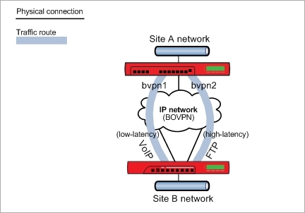
One site (Site A) has a single external interface and two branch office VPN gateways to another site (Site B) that has two external interfaces. The two network connections at Site B have different quality or cost. The objective is to send latency-sensitive traffic, such as VoIP, through the tunnel over the network with the lowest latency, and send all other traffic, such as FTP, through the other tunnel route.
Configuration Summary
On the Site A device:
- Configure a BOVPN virtual interface between Site A and the Site B external interface that uses the low-latency link. On the VPN Route tab, you do not have to add routes. The first BOVPN virtual interface is bvpn1. Make sure to select the Start Phase 1 tunnel when it is inactive check box in the BOVPN virtual interface configuration.
- Configure another BOVPN virtual interface between Site A and the second External interface at Site B. The second BOVPN virtual interface is bvpn2. You can add routes for other traffic.
- Edit the SIP policy for VoIP traffic.
- In the From list, add the network address of the local network where traffic handled by this policy originates.
- In the To list, add the network address of the trusted or optional network at the remote site where traffic handled by this policy is routed.
- Enable policy-based routing. Select the BOVPN virtual interface with a lower latency for this policy.
- For all other traffic, you can define either static routes or dynamic routes, and use the other BOVPN virtual interface that has higher latency.
On the Site B device:
- Configure a BOVPN virtual interface between the first External interface at Site B and Site A. On the VPN Route tab, you do not have to add routes. This is bvpn1 and is the low-latency link in this example. Make sure that the Start Phase 1 tunnel when it is inactive check box is selected.
- Configure a BOVPN virtual interface between Site A and the second External interface at Site B. This is bvpn2. You can add routes for other traffic.
- Edit the SIP policy for VoIP traffic.
- In the From list, add the network address of the local network where traffic handled by this policy originates.
- In the To list, add the network address of the trusted or optional network at the remote site where traffic handled by this policy is routed.
- Enable policy-based routing. Select the BOVPN virtual interface with a lower latency for this policy.
- For all other traffic, you can define either static routes or dynamic routes, and use the other BOVPN virtual interface that has higher latency.
For a detailed configuration example. see BOVPN Virtual Interface with Policy-Based Routing.
How it Works
The two BOVPN virtual interfaces each make a connection between the two sites. The source and destination addresses are specified by the policy, which is the SIP policy in this example. Although the routes are not defined in the BOVPN virtual interface settings, the SIP policy uses policy-based routing (PBR) to redirect traffic through the tunnel that has the lower latency connection. This encrypts the packets and sends the traffic through the tunnel. This configuration does not provide failover to the other tunnel because you cannot configure PBR failover from a BOVPN virtual interface to another BOVPN virtual interface.
In Fireware v11.12.2 and higher, you must configure at reverse route at Site B. For example, if a SIP connection originates at Site A and goes to Site B through the tunnel, the response traffic is sent through the same tunnel through which it was received only if a route to Site A exists at Site B.