
Related Topics
BOVPN Virtual Interface with Policy-Based Routing
You can configure policy-based routing in a policy so the policy always routes traffic through a specific BOVPN virtual interface.
Example Scenario
This example shows the configuration settings for policy-based routing of VoIP traffic between two Fireboxes. One site (Site A) has a single external interface, and two branch office VPN gateways to another site (Site B) that has two external interfaces. The two network connections at Site B have different latency. The objective is to send latency-sensitive traffic, such as VoIP through the tunnel over the network with the lowest latency. Other traffic can use either route.
Site A Firebox
For this example, the Site A Firebox has one external interface and one trusted interface.
| Interface | Type | Name | IP Address |
|---|---|---|---|
| 0 | External | External-1 | 203.0.113.2/24 |
| 1 | Trusted | Trusted | 10.0.1.1/24 |
Site B Firebox
For this example, the Site B Firebox has two external interfaces and one trusted network.
| Interface | Type | Name | IP Address |
|---|---|---|---|
| 0 (low latency connection) | External | External-1 | 198.51.100.2/24 |
| 1 | Trusted | Trusted | 10.0.100.1/24 |
| 2 (high latency connection) | External | External-2 | 192.0.2.2/24 |
BOVPN Virtual Interface Configuration
On each Firebox, configure two BOVPN virtual interfaces, one for the Site B interface with the low-latency connection and one for the Site B interface with the high-latency connection.
The BOVPN virtual interface on each Firebox must use the same settings. For this example, we assume that Site A and Site B agree to use a pre-shared key and to use all other default settings.
Site A BOVPN Virtual Interface Configuration
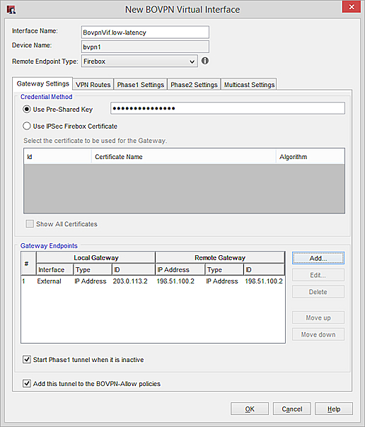
The first BOVPN virtual interface for the low latency tunnel, has these settings:
- In Fireware v11.12 or higher, a Remote Endpoint Type drop-down list appears that contains two options: Firebox, and Cloud VPN or Third-Party Gateway. To configure a tunnel between two Firebox devices, select the Firebox endpoint type, which uses the GRE protocol to encapsulate the IPSec tunnel.
- Interface Name: BovpnVif.low-latency
- The Credential Method uses the pre-shared key the two sites agreed upon.
- The Gateway Endpoints list includes one gateway endpoint pair, one for the low-latency external interface at Site B.
- Local Gateway: 203.0.113.2 (the IP address of the external interface on the Site A Firebox)
- Remote Gateway: 198.51.100.2 (the IP address of External-1 of the Site B Firebox)
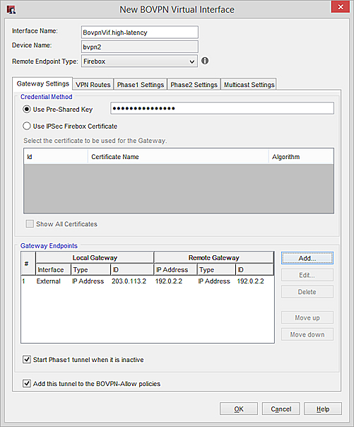
The second BOVPN virtual interface for the high latency tunnel, has these settings:
- In Fireware v11.12 or higher, a Remote Endpoint Type drop-down list appears that contains two options: Firebox, and Cloud VPN or Third-Party Gateway. To configure a tunnel between two Firebox devices, select the Firebox endpoint type, which uses the GRE protocol to encapsulate the IPSec tunnel.
- Interface Name: BovpnVif.high-latency
- The Credential Method uses the pre-shared key the two sites agreed upon.
- The Gateway Endpoints list includes one gateway endpoint pair, one for the high-latency external interface at Site B.
- Local Gateway: 203.0.113.2 (the IP address of the external interface on the Site A Firebox)
- Remote Gateway: 192.0.2.2 (the IP address of External-2 on the Site B Firebox)
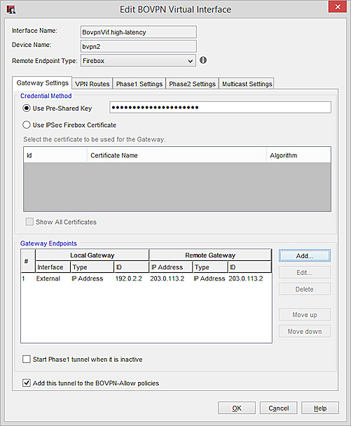
Site B BOVPN Virtual Interface Configuration
The configuration at Site B is exactly the same as at Site A, except that the local and remote gateway IP addresses are reversed
The first BOVPN virtual interface for the low latency tunnel, has these settings:
- In Fireware v11.12 or higher, a Remote Endpoint Type drop-down list appears that contains two choices: Firebox, and Cloud VPN or Third-Party Gateway. For a Firebox-to-Firebox tunnel, select the Firebox endpoint type, which uses the GRE protocol to encapsulate the IPSec tunnel.
- Interface Name: BovpnVif.low-latency
- The Credential Method uses the pre-shared key the two sites agreed upon.
- The Gateway Endpoints list includes one gateway endpoint pair, one for the low-latency external interface at Site B.
- Local Gateway: 198.51.100.2 (the IP address of External-1 of the Site B Firebox)
- Remote Gateway: 203.0.113.2 (the IP address of the external interface on the Site A Firebox)

The second BOVPN virtual interface for the high latency tunnel, has these settings:
- In Fireware v11.12 or higher, a Remote Endpoint Type drop-down list appears that contains two choices: Firebox, and Cloud VPN or Third-Party Gateway. For a Firebox-to-Firebox tunnel, select the Firebox endpoint type, which uses the GRE protocol to encapsulate the IPSec tunnel.
- Interface Name: BovpnVif.high-latency
- The Credential Method uses the pre-shared key the two sites agreed upon.
- The Gateway Endpoints list includes one gateway endpoint pair, one for the high-latency external interface at Site B.
- Local Gateway: 192.0.2.2 (the IP address of External-2 on the Site B Firebox)
- Remote Gateway: 203.0.113.2 (the IP address of the external interface on the Site A Firebox)
Policy-Based Routing Configuration
After the BOVPN virtual interfaces are established, the two sites can add use static, dynamic, or policy-based routing to send traffic through either tunnel. To make sure that SIP traffic that originates from either network always uses the tunnel with lower latency, use policy-based routing in the SIP policy at each site.
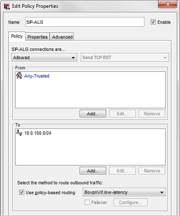
SIP Policy at Site A
The SIP policy at Site A has these settings:
- The From list has Any-Trusted. Or you could specify the interface or local network where SIP traffic originates.
- The To list has 10.0.100.0/24, the network IP address of the trusted network at Site B.
- Policy-based routing is enabled, and the BOVPN virtual interface BovpnVif.low-latency is selected.
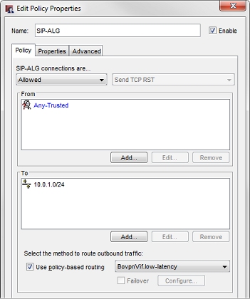
SIP Policy at Site B
The SIP policy at Site B has these settings:
- The From list has Any-Trusted. Or you could specify the interface or local network where SIP traffic originates.
- The To list has 10.0.1.0/24, the network IP address of the trusted network at Site A.
- Policy-based routing is enabled, and the BOVPN virtual interface BovpnVif.low-latency is selected.
How This Configuration Works
In this example, each Firebox has two BOVPN virtual interfaces to a peer Firebox. The SIP policy on each Firebox is configured to route connections through the BOVPN virtual interface that has the lowest latency. Policy-based routing takes precedence over any other multi-WAN or BOVPN virtual interface routes. Note that this configuration does not provide failover to the other tunnel, since you cannot configure PBR failover from a BOVPN virtual interface to another BOVPN virtual interface.
See Also
Configure a BOVPN Virtual Interface