Applies To: Locally-managed Fireboxes
The objective of this configuration example is to show how an organization with multiple sites of different sizes can establish secure VPN connections between all the sites. In this example, the organization wants the connection between any two sites to be independent of connectivity to a third site. They could have resources distributed among multiple sites, or business processes that are a good match for a decentralized architecture.
This configuration example is provided as a guide. Additional configuration settings might be necessary, or more appropriate, for your network environment.
Solution Overview
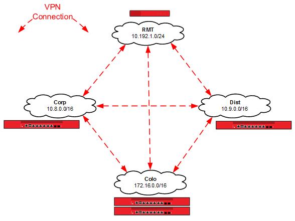
In a decentralized VPN configuration, also referred to as full mesh, each site has VPN tunnels established to all other sites. This configuration offers resiliency, because a failure at a single site impacts only the services directly dependent on it.
Reliable connectivity between network locations is especially important when one or more locations have a unique network resource that must be accessible from other network locations. As you establish additional remote locations, it may be required to expand the capacity of any site with a unique resource. If resources are located at a single site, a centralized architecture could be a better solution.
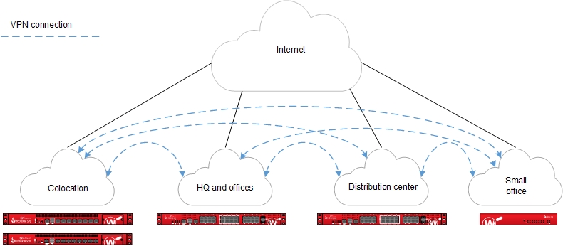
The Firebox at each site establishes a VPN connection to the Firebox at every other site.
Requirements
Reliable connectivity
While this is a fault-tolerant design, sites that host resources unique to their location should have reliable connectivity appropriate for the resources they host.
Sufficient bandwidth
Because of the encryption and encapsulation overhead, VPN bandwidth is measured at less than line speed.
A Firebox appropriate for each location
Firebox capabilities vary by model. For VPN configurations, you must consider the VPN throughput and tunnel capacity of each model. Network environment, configuration options, and other factors can also help you determine the most appropriate model for each site.
VPN throughput is the amount of data passed over the VPN per second.
VPN tunnel count is determined by the number of connected networks (as configured in tunnel routes). For offices, this is generally the number of local networks multiplied by the number of remote networks.
For more information about VPN throughput and branch office VPN tunnel capacity available for each Firebox model, see the product datasheets.
Configuration
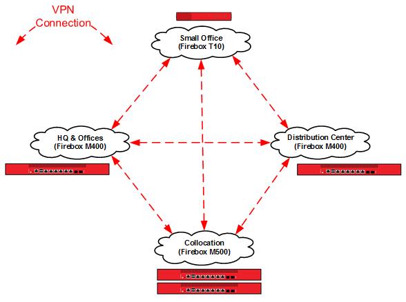
In this example, we present an example of an organization that has four locations: a colocation facility (Colo), a corporate office (Corp), a distribution center (Dist), and a small office (RMT). You can also scale up this solution to support additional offices, distribution centers, and small offices.
Topology

We use these IP addresses for the sites in our example configuration:
| Colo | Corp | Dist | RMT | |
|---|---|---|---|---|
| External interface IP address | 192.0.2.8/24 | 198.51.100.8/24 | 203.0.113.9/24 | DHCP |
| Default gateway IP address | 192.0.2.1 | 198.51.100.1 | 203.0.113.1 | DHCP |
| Private network allocated to site | 172.16.0.0/16 | 10.8.0.0/16 | 10.9.0.0/16 | 10.192.1.0/24 |
| Un-routed network allocated to site | N/A | N/A | 192.168.9.0/24 | 192.168.192.0/24 |
Configuration Files
We created four configuration files, one for each location in the example.
| Configuration File Name | Description |
|---|---|
| De-Centralized-Colo.xml | Central location for the VPNs (the colocation facility) |
| De-Centralized-Corp.xml | A corporate office |
| De-Centralized-Dist.xml | A distribution center |
| De-Centralized-RMT.xml | A small office |
How It Works
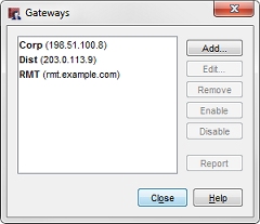
Branch Office VPN Gateways and Tunnels
For this example, we created branch office gateways and branch office tunnels defined for VPN connections between each site. Each site has three branch office VPN gateways and three branch office VPN tunnels configured.
To see the branch office VPN gateways:
- Start Policy Manager for the Firebox.
- Select VPN > Branch Office Gateways.
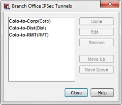
To see the branch office VPN tunnels:
- Start in Policy Manager for the Firebox.
- Select VPN > Branch Office Tunnels.
Configuration at the Colocation Site (Colo)
Configuration at the HQ Corporate Network (Corp)


Configuration at the Distribution Center (Dist)


Configuration at the Small Office (RMT)


In these images, each tunnel is named to represent the local and remote networks it manages. The identifier in parentheses is the gateway used by the tunnel.
The tunnel routes have been defined to use the subnets allocated to each site, not the individual networks defined in the site. In this configuration, the small office (RMT) only requires three tunnel routes (not six tunnel routes) to reach the trusted and optional networks at each of the other sites. Any new networks in this allocation that is established at each site are routed over the existing Branch Office VPN. For more granular control of VPN tunnels, you can define each individual network at a cost of additional tunnel routes and administration time.
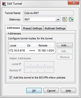

For example, the tunnel routes Colo-to-RMT and RMT-to-Colo use the subnet IP address 172.16.0.0/16 as the address of the Colo network. This enables these tunnels to manage all traffic between the small office (RMT) network and the Colo trusted (172.16.1.0) and optional (172.16.2.0) networks.
When you configure tunnel routes, it is important to remember that the local-remote pairs are defined relative to the tunnel being configured, not necessarily the network as a whole.
This diagram shows the tunnel routes configured for each VPN connection.
Conclusion
This configuration example demonstrates how to configure tunnel switching in full mesh network topology, to send VPN traffic between sites that are directly connected to each other. The VPN connection between any two sites does not rely on connectivity to a third site. This type of configuration can be a good fit for an organization that has resources distributed among multiple sites, or business processes that fit a decentralized architecture. The configuration described here can scale up to support additional sites.
This example also shows how to use subnet IP addresses in the tunnel route configuration to reduce the number of tunnels you must configure to connect private networks at each site.
Hybrid Branch Office VPN Architecture (Partial Mesh) — Configuration Example