Applies To: Locally-managed Fireboxes
Because you use routes to define what traffic to send through a BOVPN virtual interface, you can create more than one BOVPN virtual interface, and set different distances (metrics) for multiple routes to the same network. This enables you to configure BOVPN virtual interface routes through a primary tunnel that fail over to BOVPN virtual interface routes through another tunnel if the primary tunnel is not available.
Example Scenario
This example shows how to configure settings for two BOVPN virtual interfaces between Fireboxes at Site A and Site B. This configuration uses different route distances (metrics) in the BOVPN virtual interface configuration to control which BOVPN virtual interface routes are preferred.
For this example, we assume that the device at Site A has two external interfaces, and that one of the external interfaces is the preferred route for outbound traffic to Site B, either because that interface is lower cost or has faster throughput. The second external interface is used for VPN traffic only when the primary external interface is not available.
Site A Firebox
For this example, the Site A Firebox has two external interfaces, one trusted network, and one optional network.
| Interface | Type | Name | IP Address |
|---|---|---|---|
| 0 | External | External | 203.0.113.2/24 |
| 1 | Trusted | Trusted | 10.0.1.1/24 |
| 2 | Optional | Optional-1 | 10.0.2.1/24 |
| 3 | External | External-2 | 190.0.2.2/24 |
Site B Firebox
For this example, the Site B Firebox has one external interface, and one trusted network.
| Interface | Type | Name | IP Address |
|---|---|---|---|
| 0 | External | External | 198.51.100.2/24 |
| 1 | Trusted | Trusted | 10.50.1.1/24 |
BOVPN Virtual Interface Configuration
The Fireboxes at each site must have two BOVPN virtual interfaces configured. One BOVPN virtual interface uses interface 0 (External) on the Site A device, and the second BOVPN virtual interface uses interface 3 (External-2) on the Site A device. Because interface 0 is the preferred interface for VPN traffic between these devices, the primary BOVPN virtual interface that uses interface 0 has routes with a low distance (metric). This gives routes through the primary BOVPN virtual interface the highest priority, when that virtual interface is available. The same routes on the BOVPN virtual interface that use the less-preferred external interface each have a higher distance (metric), so these routes are only used if the routes through the other BOVPN virtual interface are not available.
The BOVPN virtual interfaces on each Firebox must be configured to use the same settings. For this example, we assume that Site A and Site B agree to use a pre-shared key. All other BOVPN virtual interface settings remain at the default values.
In Fireware v12.9 or higher, the Distance setting replaces the Metric setting in the VPN Routes configuration.
Site A BOVPN Virtual Interfaces
The primary BOVPN virtual interface at Site A uses these gateway settings:
- The Remote Endpoint Type is Firebox.
- The Credential Method uses the pre-shared key the two sites agreed upon.
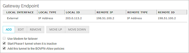
- The Gateway Endpoints list includes one gateway endpoint pair:
- External Interface: External
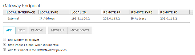
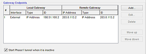
- Local Gateway: 203.0.113.2 (the IP address of the first external interface on the Site A Firebox)
- Remote Gateway: 198.51.100.2 (the IP address of the external interface on the Site B Firebox)
The configured gateway endpoint pair for the Site A primary BOVPN virtual interface in Fireware Web UI
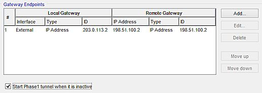
The configured gateway endpoint pair for the Site A primary BOVPN virtual interface in Policy Manager
The primary BOVPN virtual interface at Site A has one VPN route to the trusted network at Site B:
- Route to 10.50.1.0/24, Distance (Metric) 1
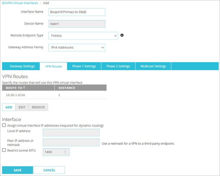
The configured VPN route for the Site A primary BOVPN virtual interface in Fireware Web UI
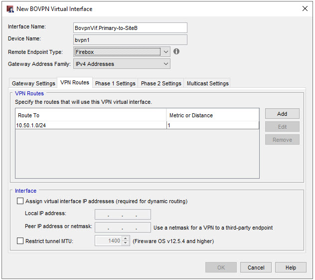
The configured VPN route for the Site A primary BOVPN virtual interface in Policy Manager
The secondary BOVPN virtual interface at Site A uses these gateway settings:
- The Remote Endpoint Type is Firebox.
- The Credential Method uses the pre-shared key the two sites agreed upon.
- The Gateway Endpoints list includes one gateway endpoint pair:
- External Interface: External-2
- Local Gateway: 190.0.2.2 (the IP address of the second external interface on the Site A Firebox)
- Remote Gateway: 198.51.100.2 (the IP address of the external interface on the Site B Firebox)
The configured gateway endpoint pair for the Site A secondary BOVPN virtual interface in Fireware Web UI
The configured gateway endpoint pair for the Site A secondary BOVPN virtual interface in Policy Manager
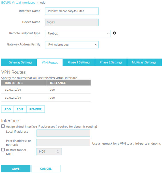
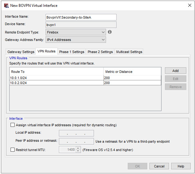
The secondary BOVPN virtual interface at Site A has one VPN route to the trusted network at Site B:
- Route to 10.50.1.0/24, Distance (Metric) 200
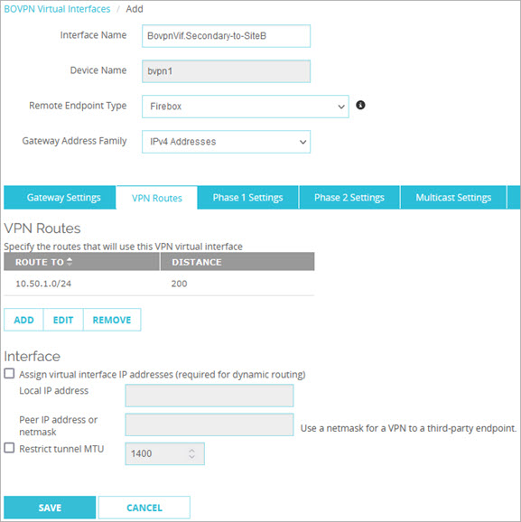
The configured VPN route for the Site A secondary BOVPN virtual interface in Fireware Web UI
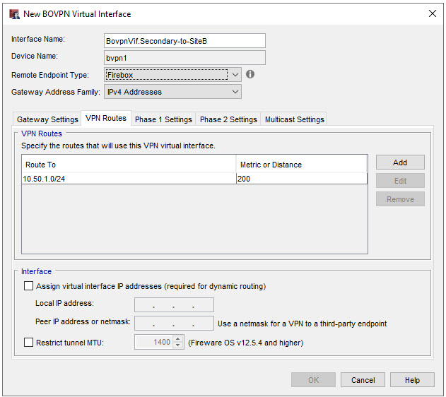
The configured VPN route for the Site A secondary BOVPN virtual interface in Policy Manager
Site B BOVPN Virtual Interfaces
The device at Site B has two BOVPN virtual interfaces.
The primary BOVPN virtual interface at Site B uses these gateway settings:
- The Remote Endpoint Type is Firebox.
- The Credential Method uses the pre-shared key the two sites agreed upon.
- The Gateway Endpoints list includes one gateway endpoint pair:
- Local Gateway: 198.51.100.2 (the IP address of the external interface on the Site B Firebox)
- Remote Gateway: 203.0.113.2 (the IP address of the first external interface on the Site A Firebox)
The gateway endpoint pair for the Site B primary BOVPN virtual interface in Fireware Web UI
The gateway endpoint pair for the Site B primary BOVPN virtual interface in Policy Manager
The primary BOVPN virtual interface at Site B has two VPN routes to the trusted and optional networks at Site A:
- Route to 10.0.1.0/24, Distance (Metric) 1
- Route to 10.0.2.0/24, Distance (Metric) 1
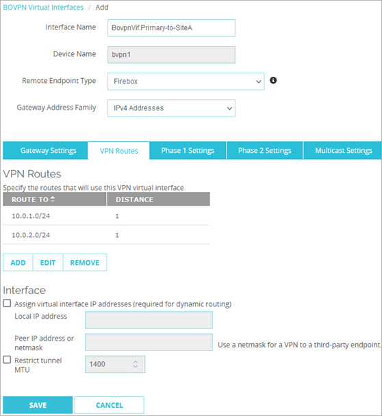
The configured VPN routes for the Site B primary BOVPN virtual interface in Fireware Web UI
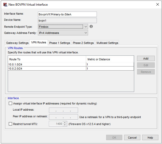
The configured VPN routes for the Site B primary BOVPN virtual interface in Policy Manager
The secondary BOVPN virtual interface at Site B, uses these gateway settings:
- The Remote Endpoint Type is Firebox.
- The Credential Method uses the pre-shared key the two sites agreed upon.
- The Gateway Endpoints list includes one gateway endpoint pair:
- Local Gateway: 198.51.100.2 (the IP address of the external interface on the Site B Firebox)
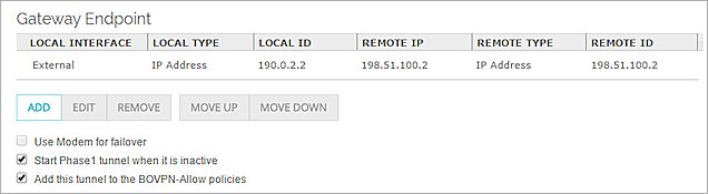
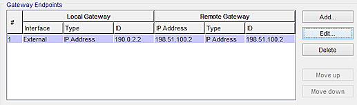
- Remote Gateway: 190.0.2.2 (the IP address of the second external interface on the Site A Firebox)
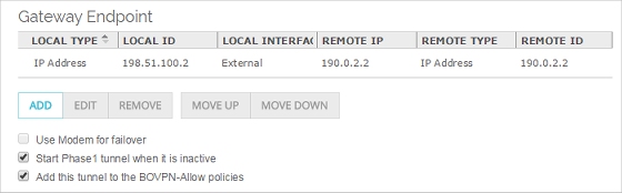
The configured gateway endpoint pair for the Site B secondary BOVPN virtual interface in Fireware Web UI
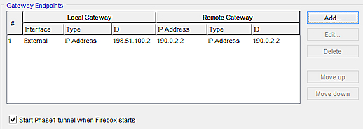
The configured gateway endpoint pair for the Site B secondary BOVPN virtual interface in Policy Manager
The secondary BOVPN virtual interface at Site B has two VPN routes to the trusted and optional networks at Site A:
- Route to 10.0.1.0/24, Distance (Metric) 200
- Route to 10.0.2.0/24, Distance (Metric) 200
The configured VPN routes for the Site B secondary BOVPN virtual interface in Fireware Web UI
The configured VPN routes for the Site B secondary BOVPN virtual interface in Policy Manager.
How This Configuration Works
In this example, each Firebox has two BOVPN virtual interfaces to a peer Firebox. The routes configured for both BOVPN virtual interfaces are the same, except for the distances (metrics). The Firebox uses the route with the lowest distance (metric), which is the route with the highest priority. This means that:
If both BOVPN virtual interfaces are available
The Firebox uses the routes through the primary BOVPN virtual interface, because those routes have the highest priority (lowest distance).
If the primary BOVPN virtual interface is not available, but the secondary BOVPN virtual interface is available
The Firebox automatically changes the distances (metrics) for routes that use the primary BOVPN virtual interface to 255, to give these routes the lowest priority. The Firebox then uses the routes through the second BOVPN virtual interface, because those routes with a distance (metric) of 200 are now the highest priority routes to that destination.
When the primary BOVPN virtual interface becomes available again
The Firebox automatically changes the route distances (metrics) for routes through the primary BOVPN virtual interface back to the configured route distance (metric), in this case 1. Traffic between the two sites automatically uses the routes through the primary BOVPN virtual interface because those routes now have higher priority.
You can optionally configure the Firebox to remove the route completely, rather than increase the distance (metric) when the route is down. For more information, go to About Global VPN Settings.