WatchGuard security appliances deliver unparalleled unified threat management, superior performance, ease of use, and value. Powerful subscription-based security services deliver in-depth defenses against advanced malware, ransomware, botnets, trojans, viruses, drive-by downloads, phishing and much more.
This guide introduces the Firebox M4800, a RoHS-compliant (lead-free) hardware product offered by WatchGuard. The Firebox M4800 consolidates critical network and security functions into a single, centrally managed device, and is ideal as the ‘hub’ for distributed, hub-and-spoke type deployment scenarios.
Fireware OS
The Firebox M4800 device uses WatchGuard’s next generation UTM OS — Fireware OS. Each Firebox M4800 device includes Fireware OS and delivers exceptional protection against today's sophisticated threats to make sure that your business stays connected. For more information on the features of Fireware OS, see Fireware Help.
About Your Hardware
Hardware Specifications
This table shows the hardware specifications for the WatchGuard Firebox M4800.
| Processor |
Intel Coffee Lake Xeon E-2176G |
| Storage | 256 GB Solid State HDD |
| Memory: DDR4 | 16 GB |
| Power Supply |
Dual power supplies |
| Dimensions |
D = 46.8 cm (18.42") |
| Weight | 8 kg (17.63 lbs) |
Interface Specifications
This table shows the interface specifications for the WatchGuard M4800 as shipped.
| Management Interface |
1x 1000 Base TX (10/100/1000Mbps), RJ45 connector |
| Network Interfaces |
8x 1000 Base TX (10/100/1000Mbps), RJ45 connector |
| I/O Interfaces | 2 USB 3.0 1 RJ45 RS232 console port |
The Firebox also has two slots where you can install additional interface modules. The supported interface modules are described in the Hardware Description section.
Environmental Requirements
To safely install your Firebox, we recommend that you:
- Install it in a network rack.
- Put it in a secure area, such as a locked room, to block the device from people who do not have permission to use it.
- Connect it to a conditioned power supply to prevent damage from sudden power changes.
This table shows other environmental requirements for the M4800 appliance.
| Operating Temperature |
0° to 40°C (32° to 104°F) |
| Operating Humidity | 5% to 90% non-condensing |
| Non-operating Temperature | –10° to 70°C (14° to 158°F) |
| Non-operating Humidity | 5% to 90%, non-condensing |
Hardware Description
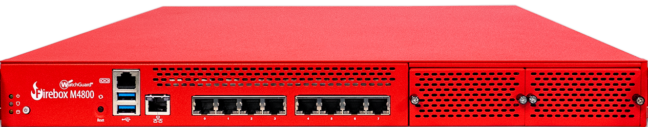
Front
Front view of the Firebox:
Left front panel detail:

Buttons and Indicators
Power (![]() )
)
The power indicator is green when the device is powered on.
Arm/Disarm (![]() )
)
When the device is armed and ready to pass traffic, this indicator is green. When the device is powered on, but not ready to pass traffic, this indicator is red.
Storage (![]() )
)
When there is activity on the internal storage, this indicator is yellow.
Power Button (![]() )
)
The Power button is lit to indicate power status. It is green when the Firebox is powered on, and red when power is available, but the Firebox is powered off.
When the Power button is red, press it to power on the Firebox.
When the Power button is green, press and hold the power button for five seconds to power off the Firebox. The Firebox does not power off if you briefly press the Power button.
Reset Button
The Reset button, located to the left of the USB interfaces, resets the device to factory-default settings. To reset the device, see Restore Factory Default Settings
Built-in Interfaces
The Firebox M4800 has eight built-in network interfaces, a management interface, two USB interfaces, and one serial console port.
Dual USB interfaces
The device includes two USB interfaces. Connect a USB storage device for USB backup and restore, or to store a support snapshot. For more information, see Fireware Help.
Console port
An RJ45 connector for the serial (console) interface is located above the USB interfaces. You can connect to this serial interface to log in to the Fireware Command Line Interface.
For more information about the command line interface, see the current Command Line Interface Reference available on the Firebox documentation page at https://www.watchguard.com/wgrd-help/documentation/xtm.
Management interface
The management interface, labeled ![]() or Mgmt, is located to the right of the USB interfaces. You must connect to this interface to configure the Firebox when it starts with factory-default settings. The management interface is interface 24.
or Mgmt, is located to the right of the USB interfaces. You must connect to this interface to configure the Firebox when it starts with factory-default settings. The management interface is interface 24.
RJ45 Ethernet interfaces
Interfaces 0 - 7 are RJ45 Ethernet interfaces that support link speeds of 10, 100, or 1000 Mbps. Each RJ45 interface has two indicators. The right indicator shows the interface connection status. The left indicator shows interface activity.
| Indicator | Indicator Color | Interface Status |
|---|---|---|
| Connection (right) |
Yellow |
Link at 1000 Mbps |
| Green | Link at 100 Mbps | |
| Not Lit | Link at 10 Mbps or no link | |
| Activity (left) | Yellow, blinks | Power on, network activity |
| Not Lit | Power off, no connections |
Interface Modules
To add more interfaces to your Firebox, you can install an interface module in an available interface module slot. You must install the interface module before you can configure the interfaces. For instructions to install or remove interface modules, see Interface Module Installation.
Caution: Interface modules are not hot-swappable. To avoid damage to the system, power off the Firebox before you install or remove interface modules.
You can purchase these compatible interface modules from an authorized WatchGuard reseller:
- WatchGuard Firebox M 8 Port 1 Gb Copper Module — WatchGuard SKU WG8592
- WatchGuard Firebox M 8 Port SFP Fiber Module — WatchGuard SKU WG8593
- WatchGuard Firebox M 4 Port 10 Gb SFP+ Fiber Module — WatchGuard SKU WG8594
- WatchGuard Firebox M 2 Port 40 Gb QSFP+ Fiber Module — WatchGuard SKU WG8023
For each interface module, ports are numbered from 0-7, 0-3, or 0-1. The interface numbers that appear in the Firebox configuration depend on the number of ports on the interface module, and the interface module slot where the interface module is installed.
| Installed in slot | Number of Ports | Modular Interface Port Numbers | Interface Numbers in Management Software |
|---|---|---|---|
| A | 8 | A0-A7 | 8-15 |
| 4 | A0-A3 | 8-11 | |
| 2 | A0-A1 | 8-9 | |
| B | 8 | B0-B7 | 16-23 |
| 4 | B0-B3 | 16-19 | |
| 2 | B0-B1 | 16-17 |
Indicators for the modular interfaces are described below.
The eight RJ45 interfaces are numbered from 0 to 7.
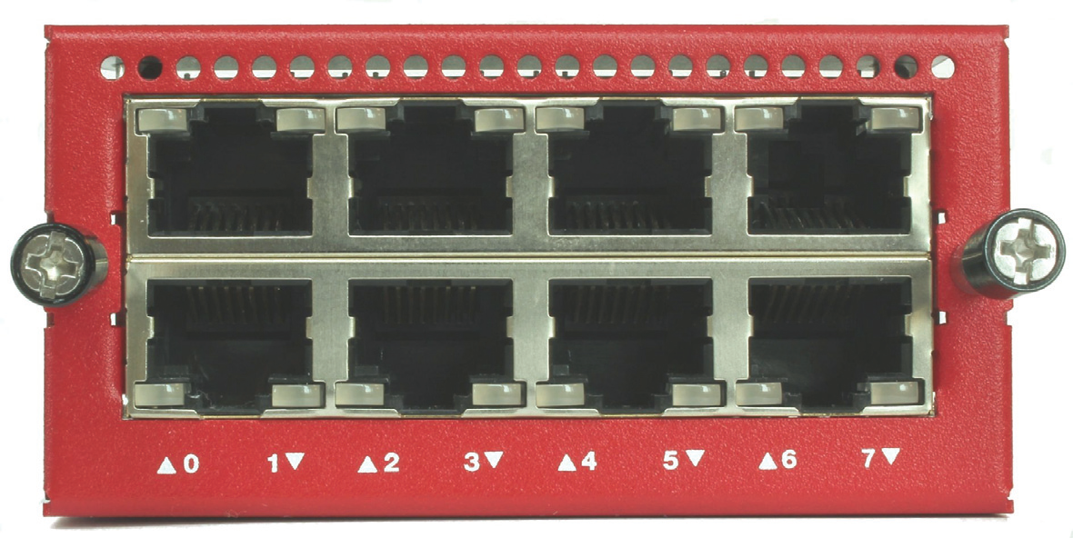
Each RJ45 interface has two indicators. The right indicator shows the interface link status. The left indicator shows interface activity.
| Indicator | Indicator Color | Interface Status |
|---|---|---|
| Connection (right) |
Yellow |
Link at 1000 Mbps |
| Green | Link at 100 Mbps | |
| Not Lit | Link at 10 Mbps or no link | |
| Activity (left) | Yellow, blinks | Power on, network activity |
| Not Lit | Power off, no connections |
The eight SFP interfaces are numbered from 0 to 7. To use these interfaces you must plug in a compatible SFP transceiver.
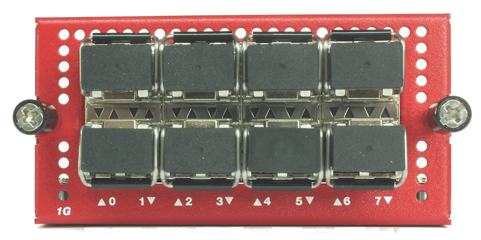
Each SFP interface has two indicators. Indicators are located in the center of the interface module, between the upper and lower row of interfaces. Indicators that point up (▲) show the status of the upper interface. Indicators that point down (▼) show the status of the lower interface
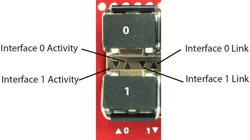
For each interface, the left indicator shows activity, and the right indicator shows the link status.
| Indicator | Indicator Color | Interface Status |
|---|---|---|
| Connection (right) |
Orange |
Link at 1000 Mbps |
| Not Lit | No link | |
| Activity (left) | Orange, blinks | Power on, network activity |
| Not Lit | Power off, no connections |
You can purchase compatible SFP transceivers from an authorized WatchGuard reseller:
SFP multi-mode transceivers (1000Base-SX, 850nm)
- FINISAR FTLF8519P3BNL
- WatchGuard SKU WG8585
The four SFP+ ports are numbered 0 - 3. To use these interfaces, you must plug in a compatible SFP+ transceiver.
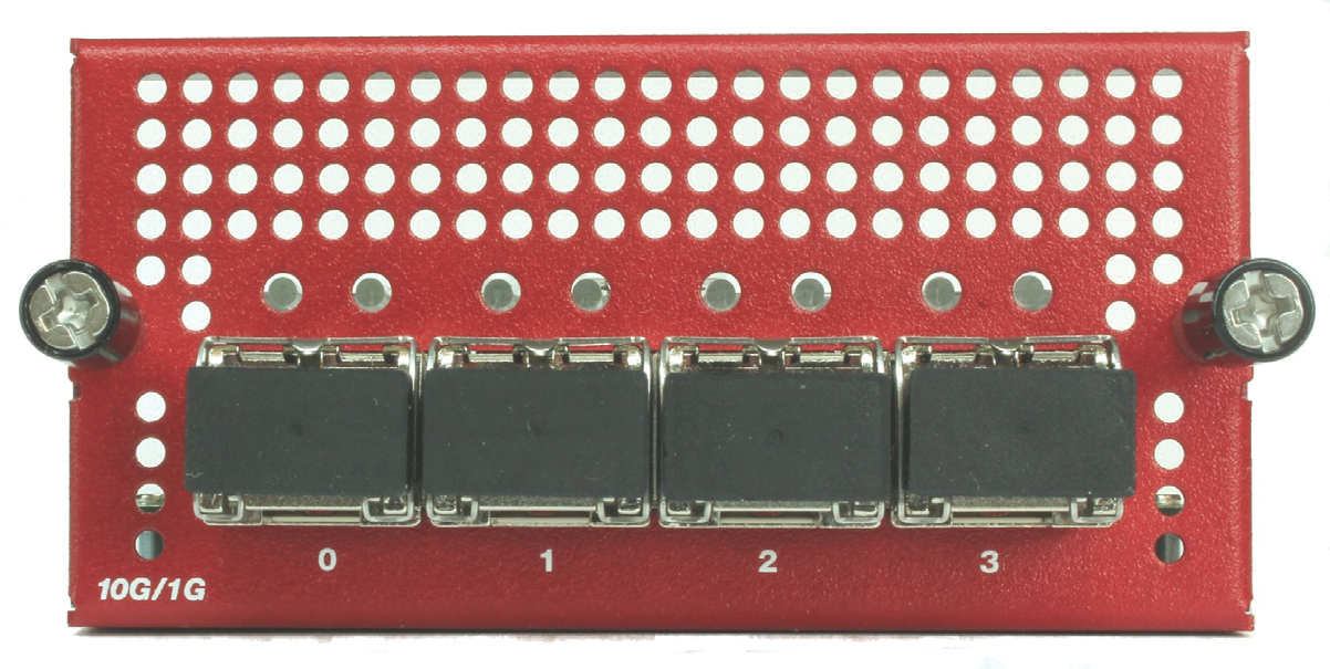
Each SFP+ port has two indicators that show link status and activity.
| Indicator | Indicator Color | Interface Status |
|---|---|---|
| Connection (left) |
Green |
Link at 10 Gbps or 1 Gbps |
| Not Lit | No link | |
| Activity (right) | Orange, blinks | Power on, network activity |
| Not Lit | Power off, no connections |
You can purchase compatible SFP transceivers from an authorized WatchGuard reseller:
SFP+ multi-mode transceiver (10GBase-SR/1000Base-SX 850 nm)
- FINISAR FTLX8571D3BCV
- FINISAR FTLX8574D3BCL
- WatchGuard SKU WG8583
SFP+ Copper transceiver (10Gbase-T, 30m)
- FS SFP-10G-T
The two QSFP+ ports are numbered 0 and 1. To use these interfaces, you must plug in a compatible QSFP+ transceiver.

Each QSFP+ port has two indicators that show link status and activity.
| Indicator | Indicator Color | Interface Status |
|---|---|---|
| Connection (right) |
Orange |
Link at 40 Gbps |
| Not Lit | No link | |
| Activity (left) | Orange, blinks | Power on, network activity |
| Not Lit | Power off, no connections |
You can purchase compatible SFP transceivers from an authorized WatchGuard reseller:
QSFP+ 40Gb multi-mode transceivers (40Gbase-SR4 150m Gen2 QSFP+)
- WatchGuard WG8022
- Finisar FTL410QE2C
- Finisar FTL410QE4C
- FS QSFP-SR4-40G
QSFP+ 40Gb single mode transceivers (40Gbase-LR4 10km QSFP+)
- Finisar FTL4C1QE2C
- Finisar FTL4C1QE3C
For a list of compatible transceivers, see Supported transceivers for Firebox Appliances in the WatchGuard Knowledge Base.
Rear
Rear view of the Firebox:

Cooling fans
The fans decrease the internal temperature of the device. The fans start at maximum RPM when the Firebox is powered on. The device adjusts the fan speed based on the external temperature and device CPU load.
Power switch
Controls the power supplied to the Firebox. The Power switch activates both power supplies.
AC receptacles
Each AC receptacle accepts a detachable AC power cord supplied with the Firebox.
WARNING: The AC power cord is only for WatchGuard products, and not usable for other equipment.
Each power supply is a WatchGuard standard auto-sensing AC power supply.
In the event of a complete power failure, the Firebox will immediately power off. When power is restored, the Firebox will power on automatically, even if the Firebox was powered off previously.
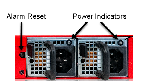
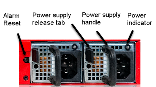
Replaceable power supplies
There are two power supplies on the Firebox M4800, each with a power indicator at the top. For instructions to install a replacement power supply, see Power Supply Installation.
| Power Indicator Color | Power Supply Status |
|---|---|
| Green flashing | Power is connected to at least one power supply, device is powered off |
| Green solid | Power is connected, device is powered on |
| Red flashing | Power is not connected or power supply failed, device is powered on |
| Not lit | Power is not connected, device is powered off |
Alarm Reset button
When the Firebox is powered on, if either power supplies fails or is not connected to a power source, an audible alarm sounds. To silence the alarm, press the alarm reset button, located to the left of the power supplies. After you silence the alarm the indicator for the failed power supply flashes red.
Restore Factory Default Settings
If you ever need to, you can restore your Firebox to its factory-default settings. For example, if you do not know the administrator account passphrase or you want to start over with a new configuration, you can reset your device. Make sure you back up your device configuration before you reset your device in case you want to restore it in the future.
To reset your device:
- Power off the device.
- Press and hold the Reset button, while you briefly press the Power button on the front of the device to power it on.
- Continue to hold the Reset button while the Arm indicator is red.
- Continue to hold the Reset button while the Arm indicator slowly flashes green.
- When the Arm indicator flashes green more rapidly, release the Reset button.
- Wait until the Arm indicator starts to flash red.
- Press and hold the Power button on the front of the device for five seconds to power off the device.
- Briefly press the Power button on the front of the device to power it on.
Hardware Installation
Your Firebox ships with a rack mount kit. It also supports user-installable components. This document includes instructions to install your Firebox and its components:
- Rack mount installation
- Interface module installation
- Power supply installation and replacement
Rack Mount Installation
Each Firebox device ships with hardware for installation in a four-post network rack.
Caution: The included rail kit and ear brackets are intended for installation in four-post network racks. For two-post racks, we recommend you use third-party shelves or heavy-duty rack ears to support the weight of the device in the rack.
- Rack rail kit
- 2 sliding rails

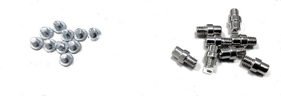
- 10 small screws and 8 large screws
- Front ear brackets to secure the device in the rack when attached to the rail kit
- 2 front ear brackets
Caution: The front ear brackets are intended to secure the device in the rack when the device is attached to the rail kit in a four-post rack. Do not use the included ear brackets to secure and support the device in a two-post rack.

- 6 small screws and 2 large screws

Precautions
When you install the device in a rack, make sure you consider these factors:
Elevated Operating Ambient Temperature
If you install the device in a closed or multi-unit rack assembly, the operating ambient temperature of the rack environment might be greater than room ambient. Make sure the ambient temperature of the rack environment is within the certified operating range specified in this Hardware Guide.
Reduced Air Flow
When you install the device in a rack, make sure that the amount of air flow required for safe operation of the equipment is not compromised.
Mechanical Loading
When you mount the device in the rack, avoid hazardous conditions caused by uneven mechanical loading.
Circuit Overloading
Make sure you connect the device to the power supply circuit in such a way that there is no overloading of the circuits, and no impact on overcurrent protection and supply wiring.
Reliable Grounding
Make sure all rack-mounted equipment is correctly grounded. For example, make sure you use power strips instead of direct connections to the branch circuit.
WARNING: Do not use your slide/rail mounted device as a shelf or work space.
- Pull out the inner rail, as shown below.
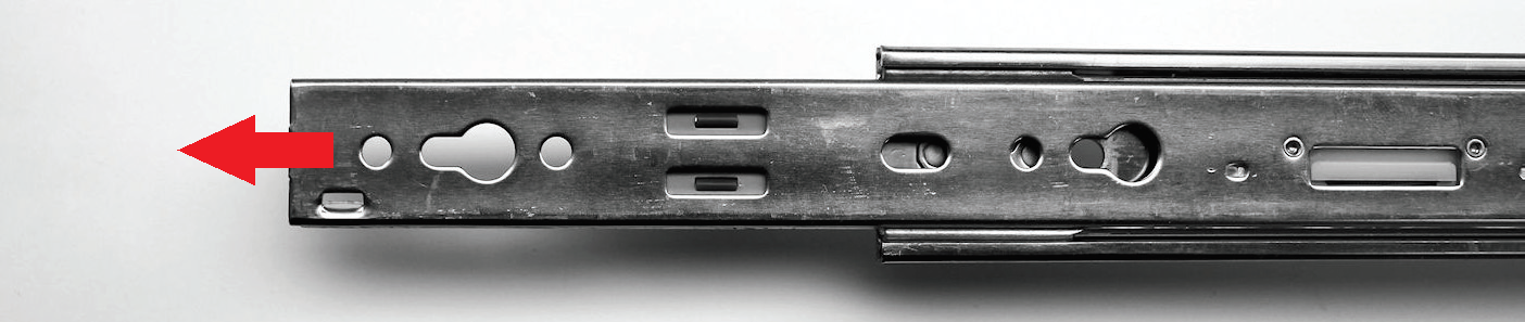
- Continue to slide the inner rail out until you hear a click.
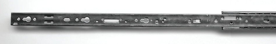
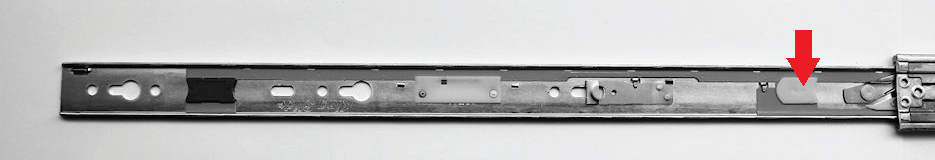
- Turn the rail over. Slide the white release tab on the inner rail away from the outer rail, and pull the inner rail from the outer rail until they completely separate.
- Repeat these steps to separate the second inner and outer rail.
- Locate the ten short screws, and the front ear brackets and screws.
- Use three of the screws provided with the front ear brackets to attach an ear bracket to the front of the Firebox on one side.
- Put the inner rail against one side of the Firebox with the small blue release tab toward the front of the Firebox, facing out.

- Align the screw holes in the rail with the five screw holes on the sides of the Firebox. The inner rail extends out from the back of the Firebox.
- Attach the inner bracket to the Firebox with five of the short screws provided in the rail kit.
- Repeat these steps to attach the other inner rail and front ear bracket to the other side of the Firebox.
You do not need to use screws to attach the rails to the network rack. To attach rails to the rack, align the screw heads on each end of the rail with holes in the rack and then latch the rail to the front and back of the rack, as described below.
To install the rails in a network rack:
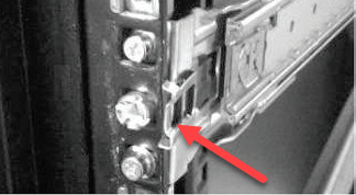
- Align the front of one rail with three available screw holes in the front edge of the rack.
- Press the end of the rail toward the rack until the metal latch in the center of the rail clicks into place around the inner edge of the rack.
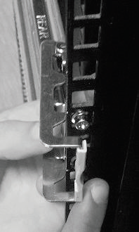
- Align the rear of the outer rail with three available screw holes in the rear of the rack.
- Pull the latch handle slightly toward the center of the rack and snap it into place around the inner edge of the rack.
- Repeat these steps to install the second sliding rail in the rack.
If the screw heads on the rail ends are too large to fit through the holes in your network rack, use the eight screws with smaller heads (included with the rail kit) to replace the screws on the rails before you install the rails in the rack.
- Remove the outer two screws on the front of the rail and replace them with two smaller screws included with the rail kit.

- Remove the two screws from the back of the rail and replace them with two smaller screws included with the rail kit.

- Repeat these steps to install smaller screws on the second rail.
- Install the rails in the rack as described in the previous procedure.
Use these steps to complete installation of the Firebox in the rack. It could require two people to safely complete these steps.
- Stand in front of the rack and hold the Firebox with its front facing you.
- Align the inner rails on each side of the Firebox with the outer rail on each side of the rack.
- Slide the Firebox into the rack as far as possible.
- Slide the blue slide rail locks on the inner rails toward the front and slide the Firebox farther into the rack, until the front ear brackets touch the front of the rack.
- You can use the larger screws included with the rack ears to attach the rack ear brackets to the rack if you do not plan to frequently pull this device out of the rack.
You must release the slide rail locks to remove the Firebox from the rack. It could require two people to remove the device from the rack. The slide rail locks are blue tabs on the inner rails on each side of the Firebox.
To remove the Firebox from the rack:
- Remove any screws that attach the mounting bracket to the front of the rack.
- Gently pull the device out about half way.
- Slide the blue rail locks on the inner rails toward the front of the Firebox and pull the Firebox completely out of the rack.
Interface Module Installation
You can install two additional interface modules in slots A and B of your Firebox. The supported interface modules are described in detail in the Interface Modules section.
Caution: Interface modules are not hot-swappable. To avoid damage to the system, power off the Firebox before you install or remove interface modules.
Install an Interface Module
To install an interface module:
- Disconnect the power cables from the Firebox.
- Loosen the two captive screws on the slot cover.
- Remove the slot cover to expose the interface slot.
- Insert the interface module into the slot, and push it firmly into place.
- Tighten the two captive screws on the interface module to attach the interface to the Firebox.
- Reconnect the power cables to the Firebox.
The Firebox starts automatically. When the Firebox starts, Fireware automatically detects all installed interfaces.
Remove an Interface Module
Caution: Before you remove an installed interface module, make sure that the interfaces on that module are not enabled in the Firebox configuration. You cannot manage a Firebox if an enabled interface has been removed.
To remove an installed interface module:
- Disconnect the power cables from the Firebox.
- Disconnect all network cables from the installed interface module.
- Loosen the two screws on the installed interface module.
- Slide the interface module out of the slot.
- Place the removed interface module on an antistatic surface, or immediately install it in another slot.
- Install a slot cover over the empty slot or install another interface module. The slot cover keeps dust out of the Firebox.
Power Supply Installation and Replacement
The Firebox has two redundant hot-swappable power supplies. If a power supply fails, you can replace it while the Firebox is powered by the other power supply.
To replace a power supply:
- Use the power indicator to identify the failed power supply. If the device is powered on, the indicator on the failed power supply flashes red after you reset the audible alarm.
- Disconnect the power cable from the power supply you want to replace.
- Find the release tab, located on the left side of the power supply.
- Firmly push the release tab to the right, while you use the power supply handle to pull the power supply out of the slot.
- Slide the replacement power supply into the open slot.
- Press firmly on the face of the power supply until it is flush with the back of the Firebox. If the replacement is successful, the power indicator light for the new power supply is green.
You can purchase a replacement power supply from an authorized WatchGuard reseller.
- WatchGuard Firebox M4800 Hot Swap Power Supply — WatchGuard SKU WG9012
Notices
All WatchGuard products are designed and tested to meet strict safety requirements. These requirements include product safety approvals and other global compliance standards. Read these instructions carefully before you operate the product, and refer to them as needed for continued safe operation of your product.
Product Safety Certification
The WatchGuard product is safety certified under the following standards:
- CAN/CSA C22.2 No.60950-1-07, Second Edition 2014-10
- UL 60950-1, Second Edition 2014-10-14
- IEC 60950-1, 2005+A1:2009+A2:2013
- IEC 62368-1: 2014 2nd edition
- EN 60950-1:2006+A11:2009+A1:2010+A12:2011+A2:2013
Safety Warning
- The AC power cord is only for WatchGuard products, and not usable for other equipment.
本コードは本製品専用です。他の機器には使用しないでください - Do not place objects on the power cord.
- Do not obstruct the ventilation openings. These openings prevent overheating of the machine.
- Never push objects of any kind into slots or openings on this equipment. Making a contact with a voltage point or shorting out a part may result in fire or electrical shock.
- When removing or installing an appliance, follow the general installation safety instructions.
- You must disconnect the AC power cord from the Firebox before you remove the cover of the Firebox for any reason.
- There is risk of explosion if the battery is replaced by an incorrect type. Dispose of used batteries according to the manufacturer’s instructions.
警示 本電池如果更換不正確會有爆炸的危險,請勿自行更換電池 - Class I Equipment. This equipment must be earthed. The power plug must be connected to a properly wired earth ground socket outlet. An improperly wired socket outlet could place hazardous voltages on accessible metal parts.
- All Ethernet cables are designed for intra-building connection to other equipment. Do not connect these ports directly to communication wiring or other wiring that exits the building where the appliance is located.
- Disconnect the power source prior to defeating or bypassing the equipment protection means (like enclosure), and to restore the equipment protection means before restoring power.
Disclaimer
WatchGuard shall not be held liable if the end user alters, modifies, or repairs any WatchGuard hardware appliance.
Hinweise Zur Sicherheit
Alle WatchGuard Produkte werden entwickelt und getestet, um strenge Sicherheitsanforderungen zu erfüllen. Diese Anforderungen umfassen Produktsicherheit Zulassungen und andere globale Compliance-Standards. Bitte lesen Sie die folgenden Anweisungen sorgfältig, bevor Sie das Produkt, und bezeichnen sie als notwendig, um den sicheren Betrieb des Geräts zu gewährleisten. Weitere Informationen finden Sie in der elektronischen Hardware Guide.
Die WatchGuard Produkt ist Sicherheit unter den folgenden Normen zertifiziert
- CAN/CSA C22.2 No.60950-1-07, Second Edition 2014-10
- UL 60950-1, Second Edition 2014-10-14
- IEC 60950-1:2005+A1:2009+A2:2013
- IEC 62368-1: 2014 2nd edition
- EN 60950-1:2006+A11:2009+A1:2010+A12:2011+A2:2013
Sicherheitshinweis
- Das Netzkabel ist nur für WatchGuard-Produkte und nicht für andere Geräte geeignet.
- Legen Sie keine Gegenstände auf das Netzkabel.
- Verdecken Sie nicht die Lüftungsöffnungen. Diese Öffnungen verhindern eine Überhitzung der Maschine.
- Stecken Sie niemals Gegenstände jeglicher Art in die Schlitze oder Öffnungen des Geräts stecken. Der Kontakt mit einem spannungsführenden Punkt oder das Kurzschließen eines Bauteils kann zu einem Brand oder elektrischen Schlag führen.
- Beim Entfernen oder Installieren eines Gerätes, nach den allgemeinen Installation Sicherheitshinweise.
Avis de sécurité
Tous les produits de WatchGuard sont conçus et testés pour répondre à des exigences de sécurité strictes. Ces exigences incluent l'homologation de la sécurité du produit et la conformité à d'autres normes globales. Lisez ces instructions avec attention avant de mettre en route l'appareil et reportez-vous-y au besoin pour assurer une utilisation sûre de l'appareil.
Certifications de sécurité du produit
Les produits de WatchGuard répondent aux normes suivantes;
- CAN/CSA C22.2 No.60950-1-07, Second Edition 2014-10
- UL 60950-1, Second Edition 2014-10-14
- IEC 60950-1:2005+A1:2009+A2:2013
- IEC 62368-1: 2014 2nd edition
- EN 60950-1:2006+A11:2009+A1:2010+A12:2011+A2:2013
Avertissement de sécurité
- Le cordon d'alimentation secteur est uniquement destiné aux produits WatchGuard et ne peut pas être utilisé pour d'autres équipements.
- Ne placez aucun objet sur le cordon d'alimentation.
- N'obstruez pas les ouvertures de ventilation. Ces ouvertures préviennent la surchauffe de l'appareil.
- N'insérez jamais d'objet de quelque sorte dans les fentes d'ouverture de cet équipement. Si vous faites contact avec un point sous tension ou court-circuitez un composant, cela peut causer un incendie ou un choc électrique.
- Si l'appareil est fourni avec un câble d'alimentation électrique à trois points (avec prise terre), le câble d'alimentation doit impérativement être branché sur une prise à trois points correctement mise à la terre.
- Quand vous enlevez ou désinstallez un équipement, suivez les instructions générales de sécurité fournies dans ce Guide Matériel pour éviter toute blessure ou dégât à l'appareil.
- La batterie au lithium utilisée dans cet appareil de sécurité réseau ne peut pas être remplacée par l'utilisateur final. Renvoyez cet appareil à un centre de service autorisé par WatchGuard pour un remplacement avec une batterie du même type ou de type équivalent recommandé par le fabricant. Si pour une raison quelconque la batterie ou cet équipement doit être mis au rebus, suivez les recommandations du fabricant de la batterie.
Aviso De Seguridad
Todos los productos WatchGuard están diseñados y probados para satisfacer estrictos requisitos de seguridad. Estos requisitos incluyen la homologación de productos de seguridad y otras normas de cumplimiento global. Por favor, lea atentamente las siguientes instrucciones antes de utilizar el producto, y se refieren a ellos como sea necesario para garantizar el funcionamiento seguro y continuo de su producto. Información adicional se puede encontrar en la Guía del usuario electrónica.
Certificación de seguridad del producto
El producto tiene certificación de seguridad WatchGuard bajo las siguientes normas:
- CAN/CSA C22.2 No.60950-1-07, Second Edition 2014-10
- UL 60950-1, Second Edition 2014-10-14
- IEC 60950-1:2005+A1:2009+A2:2013
- IEC 62368-1: 2014 2nd edition
- EN 60950-1:2006+A11:2009+A1:2010+A12:2011+A2:2013
Advertencia de seguridad
- El cable de alimentación de CA es solo para productos WatchGuard y no se puede usar para otros equipos.
- No coloque objetos sobre el cable de alimentación.
- No obstruya las aberturas de ventilación. Estas aberturas evitan el sobrecalentamiento de la máquina.
- Nunca introduzca objetos de ningún tipo en las ranuras o aberturas del equipo. El contacto con puntos de voltaje o el cortocircuito de una pieza podría provocar un incendio o una descarga eléctrica.
- Al extraer o instalar un electrodoméstico, siga las instrucciones generales de instalación de seguridad.
CE Notice
The ![]() symbol on your WatchGuard Technologies equipment indicates that it is in compliance with the Electromagnetic Compatibility (EMC) directive and the Low Voltage Directive (LVD) of the European Union (EU).
symbol on your WatchGuard Technologies equipment indicates that it is in compliance with the Electromagnetic Compatibility (EMC) directive and the Low Voltage Directive (LVD) of the European Union (EU).
RoHS Statement
The member states of the European Union approved directive 2002/95/EC, Restrictions of Hazardous Substances (“RoHS directive”‘) that became valid on July 1, 2006. It states that all new electrical and electronic equipment put on the market within the member states must not contain certain hazardous materials. This device complies with the European Union’s R0HS directive 2002/95/EC and similar regulations that may be adopted by other countries for European Sales.
WEEE Statement
WatchGuard asks that all our products to be recycled at the end of their current use to comply with local waste compliance requirements.
WatchGuard supports the EU Waste Electrical and Electronic Equipment (WEEE) Directive (2012/19/EU). That means that WEEE may not be disposed as unsorted municipal waste but is to be collected separately.
WatchGuard products are therefore labeled with this symbol:

The WEEE symbol on your WatchGuard equipment indicates that it should not be disposed of by the end user with unsorted municipal waste, but in a manner consistent with required EU Directives, and the local transposition of the Directive in the end user's jurisdiction. The symbol is placed per CENELEC standard EN50419.
WEEE may contain hazardous substances which may negatively affect the environment and human health when disposed of through normal channels. Batteries that are not enclosed in the waste equipment must be separated from it and disposed of separately before being handed in at a collection point. Old batteries, and in certain cases also the waste equipment, can likewise be returned free of charge to the point of sale. You are responsible for deleting any personal data on the waste equipment. WatchGuard is committed to reduce the negative environmental and human health effects of WEEE which will help prevent potential negative consequences for the environment and human health. If you are a consumer please use your local recycling option. This is usually your municipal refuse site.
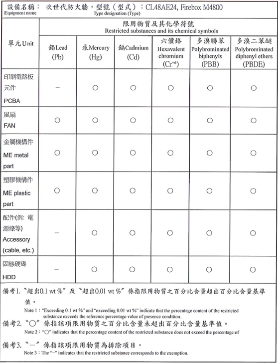
Taiwan RoHS
Limited Hardware Warranty
This Limited Hardware Warranty (the “Warranty”) applies to the enclosed hardware product, not including any associated software, which is licensed pursuant to a separate end-user license agreement and warranty (the “Product”). BY USING THE PRODUCT, YOU (either an individual or a single entity) AGREE TO THE TERMS HEREOF.
If you do not agree to these terms, please return this package, along with proof of purchase, to the authorized dealer from which you purchased it for a full refund. WatchGuard Technologies, Inc. (“WatchGuard”) and you agree as set forth below or on the reverse side of this card, as applicable.
- LIMITED WARRANTY. WatchGuard warrants that upon delivery and for one (1) year thereafter (the “Warranty Period”): (a) the Product will be free from material defects in materials and workmanship, and (b) the Product, when properly installed and used for its intended purpose and in its intended operating environment, will perform substantially in accordance with WatchGuard applicable specifications.
This warranty does not apply to any Product that has been: (i) altered, repaired or modified by any party other than WatchGuard except for the replacement or inclusion of specified components authorized in, and performed in strict accordance with, documentation provided by WatchGuard; or (ii) damaged or destroyed by force majeure events, accidents, power spikes or similar events or by any intentional, reckless or negligent acts or omissions of any party. You may have additional warranties with respect to the Product from the manufacturers of Product components. However, you agree not to look to WatchGuard for, and hereby release WatchGuard from any liability for, performance of, enforcement of, or damages or other relief on account of, any such warranties or any breach thereof.
- REMEDIES. If any Product does not comply with the WatchGuard warranties set forth in Section 1 above, WatchGuard will, following the receipt of the product you claim is defective and at its option, either (a) repair the Product, or (b) replace the Product with a like or similar product; provided, that you will be responsible for returning the Product and for all costs of shipping and handling. Repair or replacement of the Product shall not extend the Warranty Period. Any Product, component, part or other item replaced by WatchGuard becomes the property of WatchGuard. WatchGuard shall not be responsible for return of or damage to any software, firmware, information or data contained in, stored on, or integrated with any returned Products.
- DISCLAIMER AND RELEASE. THE WARRANTIES, OBLIGATIONS AND LIABILITIES OF WATCHGUARD, AND YOUR REMEDIES, SET FORTH IN PARAGRAPHS 1 AND 2 ABOVE ARE EXCLUSIVE AND IN SUBSTITUTION FOR, AND YOU HEREBY WAIVE, DISCLAIM AND RELEASE ANY AND ALL OTHER WARRANTIES, OBLIGATIONS AND LIABILITIES OF WATCHGUARD AND ALL OTHER RIGHTS, CLAIMS AND REMEDIES YOU MAY HAVE AGAINST WATCHGUARD, EXPRESS OR IMPLIED, ARISING BY LAW OR OTHERWISE, WITH RESPECT TO ANY NONCONFORMANCE OR DEFECT IN THE PRODUCT (INCLUDING, BUT NOT LIMITED TO, ANY IMPLIED WARRANTY OF MERCHANTABILITY OR FITNESS FOR A PARTICULAR PURPOSE, ANY IMPLIED WARRANTY ARISING FROM COURSE OF PERFORMANCE, COURSE OF DEALING, OR USAGE OF TRADE, ANY WARRANTY O NONINFRINGEMENT, ANY WARRANTY OF UNINTERRUPTED OR ERROR-FREE OPERATION, ANY OBLIGATION, LIABILITY, RIGHT, CLAIM OR REMEDY IN TORT, WHETHER OR NOT ARISING FROM THE NEGLIGENCE (WHETHER ACTIVE, PASSIVE OR IMPUTED) OR FAULT OF WATCHGUARD OR FROM PRODUCT LIABILITY, STRICT LIABILITY OR OTHER THEORY, AND ANY OBLIGATION, LIABILITY, RIGHT, CLAIM OR REMEDY FOR LOSS OR DAMAGE TO, OR CAUSED BY OR CONTRIBUTED TO BY, THE PRODUCT).
- LIMITATION AND LIABILITY. WATCHGUARD’S LIABILITY (WHETHER ARISING IN CONTRACT (INCLUDING WARRANTY), TORT (INCLUDING ACTIVE, PASSIVE OR IMPUTED NEGLIGENCE AND STRICT LIABILITY AND FAULT) OR OTHER THEORY) WITH REGARD TO ANY PRODUCT WILL IN NO EVENT EXCEED THE PURCHASE PRICE PAID BY YOU FOR SUCH PRODUCT. THIS SHALL BE TRUE EVEN IN THE EVENT OF THE FAILURE OF ANY AGREED REMEDY. IN NO EVENT WILL WATCHGUARD BE LIABLE TO YOU OR ANY THIRD PARTY (WHETHER ARISING IN CONTRACT (INCLUDING WARRANTY), TORT (INCLUDING ACTIVE, PASSIVE OR IMPUTED NEGLIGENCE AND STRICT LIABILITY AND FAULT) OR OTHER THEORY) FOR COST OF COVER OR FOR ANY INDIRECT, SPECIAL, INCIDENTAL, OR CONSEQUENTIAL DAMAGES (INCLUDING WITHOUT LIMITATION LOSS OF PROFITS, BUSINESS, OR DATA) ARISING OUT OF OR IN CONNECTION WITH THIS WARRANTY OR THE USE OF OR INABILITY TO USE THE PRODUCT, EVEN IF WATCHGUARD HAS BEEN ADVISED OF THE POSSIBILITY OF SUCH DAMAGES. THIS SHALL BE TRUE EVEN IN THE EVENT OF THE FAILURE OF ANY AGREED REMEDY.
- MISCELLANEOUS PROVISIONS. This Warranty will be governed by the laws of the state of Washington, U.S.A., without reference to its choice of law rules. The provisions of the 1980 United Nations Convention on Contracts for the International Sales of Goods, as amended, shall not apply. You agree not to directly or indirectly transfer the Product or use of the product or associated documentation to any country to which such transfer would be prohibited by the U.S. Export laws and regulations. If any provision of this Warranty is found to be invalid or unenforceable, then the remainder shall have full force and effect and the invalid provision shall be modified or partially enforced to the maximum extent permitted by law to effectuate the purpose of this Warranty. This is the entire agreement between WatchGuard and you relating to the Product, and supersedes any prior purchase order, communications, advertising or representations concerning the Product AND BY USING THE PRODUCT YOU AGREE TO THESE TERMS. IF THE PRODUCT IS BEING USED BY AN ENTITY, THE INDIVIDUAL INDICATING AGREEMENT TO THESE TERMS BY USING THE PRODUCT REPRESENTS AND WARRANTS THAT (A) SUCH INDIVIDUAL IS DULY AUTHORIZED TO ACCEPT THE WARRANTY ON BEHALF OF THE ENTITY AND TO BIND THE ENTITY TO THE TERMS OF THIS WARRANTY; (B) THE ENTITY HAS THE FULL POWER, CORPORATE OR OTHERWISE, TO ENTER INTO THE WARRANTY AND PERFORM ITS OBLIGATIONS UNDER THE WARRANTY AND; (C) THE WARRANTY AND THE PERFORMANCE OF THE ENTITY’S OBLIGATIONS UNDER THE WARRANTY DO NOT VIOLATE ANY THIRD-PARTY AGREEMENT TO WHICH THE ENTITY IS A PARTY.
No change or modification of the Warranty will be valid unless it is in writing and is signed by WatchGuard.
Declaration of Conformity