
Related Topics
Define a New VLAN
Before you create a new VLAN, make sure you understand all the VLAN concepts and restrictions, as described in About Virtual Local Area Networks (VLANs).
Configure a VLAN in Fireware Web UI
When you configure a VLAN in Fireware Web UI, you must select a VLAN tag setting for at least one VLAN interface. Before you create the VLAN, you must configure at least one interface as a VLAN interface.
- Select Network > Interfaces.
- Select the interface that is connected to your VLAN switch. Click Edit.
- From the Interface Type drop-down list, select VLAN.
- Click Save.
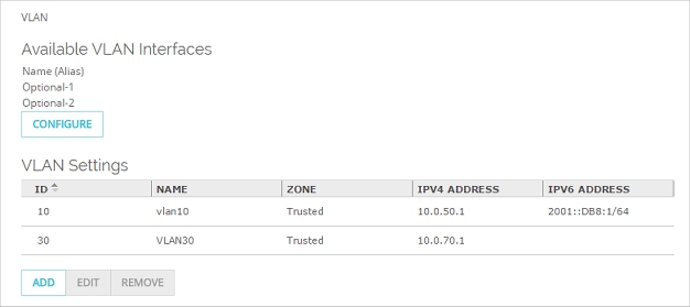
- Select Network > VLAN.
The VLAN page appears, with a list of existing user-defined VLANs and their settings.
You can also configure network interfaces from the Interfaces list.
- Click Add.
The VLAN Settings page appears.
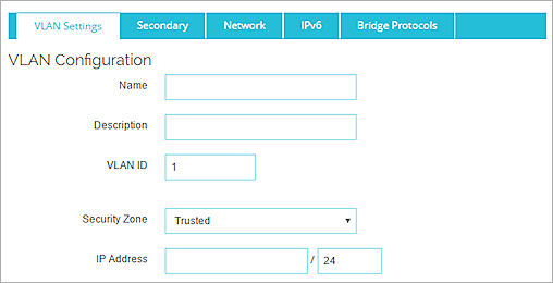
- In the Name text box, type a name for the VLAN. The name cannot contain spaces.
- (Optional) In the Description text box, type a description of the VLAN.
- In the VLAN ID text box, or type or select a value for the VLAN.
- In the Security Zone text box, select Trusted, Optional, Custom, or External.
Security zones correspond to aliases for interface security zones. For example, VLANs of type Trusted are handled by policies that use the alias Any-Trusted as a source or destination. - In the IP Address text box, type the address of the VLAN gateway.
Any computer in this new VLAN must use this IP address as its default gateway. - In the Select a VLAN tag setting for each interface list, select one or more interfaces.
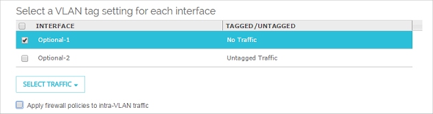
- From the Select Traffic drop-down list, select an option to apply to the selected interfaces:
- Tagged traffic — The interface sends and receives tagged traffic.
- Untagged traffic — The interface sends and receives untagged traffic.
- No traffic — Remove the interface from this VLAN configuration.
- Click Save.
Configure a VLAN in Policy Manager
In Policy Manager, you must create the VLAN before you can configure interfaces as a member of that VLAN. The VLAN configuration settings in Policy Manager do not include the list of interfaces that are members of the VLAN.
- Select Network > Configuration.
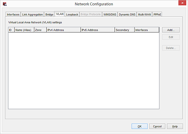
The Network Configuration dialog box appears. - Select the VLAN tab.
A table of existing user-defined VLANs and their settings appears.
- Click Add.
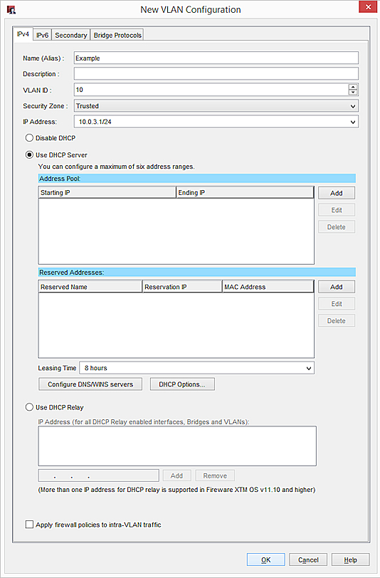
The New VLAN Configuration dialog box appears.
- In the Name (Alias) text box, type a name for the VLAN.
- (Optional) In the Description text box, type a description of the VLAN.
- In the VLAN ID text box, or type or select a value for the VLAN.
- In the Security Zone text box, select Trusted, Optional, Custom, or External.
Security zones correspond to aliases for interface security zones. For example, VLANs of type Trusted are handled by policies that use the alias Any-Trusted as a source or destination. - In the IP Address text box, type the address of the VLAN gateway.
Any computer in this new VLAN must use this IP address as its default gateway.
After you create the VLAN, you can configure interfaces as a member of the VLAN. For more information, see Assign Interfaces to a VLAN
See which interfaces are members of the VLAN
On the VLAN tab, you can see a summary of the VLAN configuration, and a list of interfaces that are members of the VLAN.
On the VLAN tab, the numbers in the Interfaces column show the physical interfaces that are members of this VLAN. The interface number in bold is the interface that sends untagged data to that VLAN.
Use DHCP on a VLAN
For a VLAN in the Trusted, Optional, or Custom security zone, you can configure the Firebox as a DHCP server for the computers on your VLAN network.
- Select the Network tab.
- From the DHCP Mode drop-down list, select DHCP Server. If necessary, type your domain name to supply it to the DHCP clients.
- To add an IP address pool, type the first and last IP addresses in the pool. Click Add.
You can configure a maximum of six address pools. - To reserve a specific IP address for a client, type the IP address, reservation name, and MAC address for the device. Click Add.
- To change the default lease time, from the drop-down list at the top of the page, select a different time interval.
This is the time interval that a DHCP client can use an IP address that it receives from the DHCP server. When the lease time is about to expire, the client sends a request to the DHCP server to get a new lease. - To add DNS or WINS servers to your DHCP configuration, type the server address in the text box adjacent to the list. Click Add.
- To delete a server from the list, select the server from the list and click Remove.
- In the New VLAN Configuration dialog box, select Use DHCP Server. If necessary, type your domain name to supply it to the DHCP clients.
- To add an IP address pool, in the Address Pool section, click Add and type the first and last IP addresses assigned for distribution. Click OK.
You can configure a maximum of six address pools. - To reserve a specific IP address for a client, in the Reserved Addresses section, click Add. Type a name for the reservation, the IP address you want to reserve, and the MAC address of the client’s network card. Click OK.
- To change the default lease time, from the Leasing Time drop-down list, select a different time interval.
This is the time interval that a DHCP client can use an IP address that it receives from the DHCP server. When the lease time is about to expire, the client sends a request to the DHCP server to get a new lease. - To add DNS or WINS servers to your DHCP configuration, click Configure DNS/WINS Servers.
- To configure DHCP options, click DHCP Options.
For more information about per-interface DNS/WINS and DHCP options, see Configure an IPv4 DHCP Server.
Use DHCP Relay on a VLAN
- On the Network tab, from the DHCP Mode drop-down list, select DHCP Relay.
- Add the IP addresses of up to three DHCP servers.
- In the New VLAN Configuration dialog box, select Use DHCP Relay.
- Add the IP addresses of up to three DHCP servers.
Make sure to add a route to the DHCP server, if necessary.
Apply Firewall Policies to Intra-VLAN Traffic
You can configure more than one Firebox interface as a member of the same VLAN. For an example of this type of configuration, see Configure One VLAN Bridged Across Two Interfaces.
To apply firewall policies to VLAN traffic between local interfaces, select the Apply firewall policies to intra-VLAN traffic check box.
Intra-VLAN traffic is traffic from a VLAN that is destined for the same VLAN. When you enable this feature, the Firebox applies policies to traffic that passes through the firewall between hosts that are on the same VLAN. If you want to apply policies to intra-VLAN traffic, make sure that no alternate path exists between the source and destination. The VLAN traffic must go through the Firebox in order for firewall policies to apply.
On an external VLAN interface, you must enable this setting so that the Firebox can:
- Apply policy based routing and VPN tunnel routes to traffic received and sent by the same external VLAN interface
- Apply firewall policies and NAT to traffic received and sent by the same external VLAN interface
Intra-VLAN policies are applied by IP address, user, or alias. If the intra-VLAN traffic does not match any defined policy, the traffic is denied as unhandled packets. Intra-VLAN non-IP packets are allowed.
Configure Network Settings for a VLAN on the External Interface
When you configure a VLAN on the external interface, you must configure how the VLAN gets the external IP address.
- On the VLAN Settings tab, from the Security Zone drop-down list, select External.
- Select the Network tab.
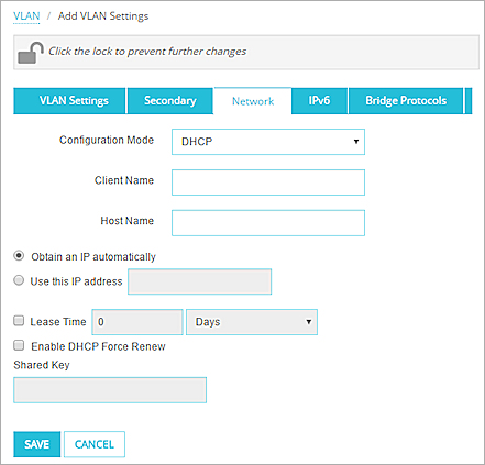
- From the Configuration Mode drop-down list, select Static IP, DHCP, or PPPoE.
- Configure the network settings with the same method you use for other external interfaces.
For more information, see Configure an External Interface.
- From the Security Zone drop-down list, select External.
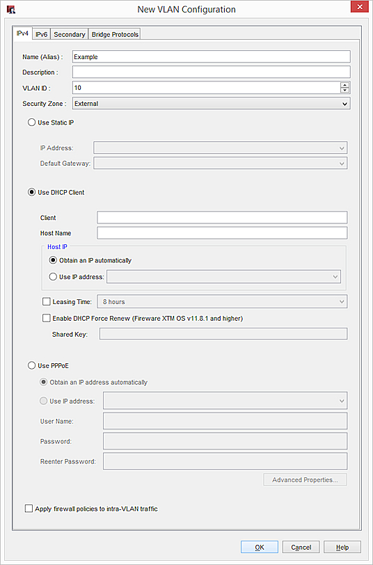
- Select an option: Use Static IP, Use DHCP Client, or Use PPPoE.
- Configure the network settings with the same method you use for other external interfaces.
For more information, see Configure an External Interface.
Enable IPv6 on a VLAN
To enable IPv6 on a VLAN interface:
- Select the IPv6 tab.
- Select the Enable IPv6 check box.
- Configure the IPv6 network settings the same as you would for any other interface.
For information about how to configure the IPv6 settings, see
Configure a VLAN Secondary IP Addresses
- Select the Secondary tab.
- Type an unassigned host IP address in slash notation from the secondary network.
- Click Add.
- Select the Secondary tab.
- Click Add.
- Type an unassigned host IP address from the secondary network.
- Click OK.
For more information about secondary interface IP addresses, see Add a Secondary Network IP Address.
Enable Spanning Tree Protocol
In Fireware v11.12.2 and higher, you can enable Spanning Tree Protocol for some VLAN configurations. Not all VLAN configurations are supported. For more information about Spanning Tree Protocol, see About Spanning Tree Protocol.
To change the default Spanning Tree Protocol settings, you must use the Fireware command line interface (CLI). For more information about the default Spanning Tree Protocol settings, see Configure Spanning Tree Protocol Settings in the CLI.
To enable Spanning Tree Protocol from the Web UI:
- Click the Bridge Protocols tab.
- Select Enable Spanning Tree Protocol.
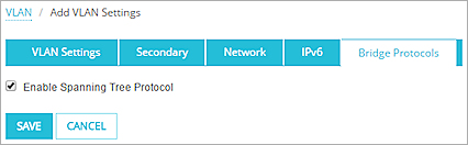
- Click Save.
To enable Spanning Tree Protocol in Policy Manager:
- Click the Bridge Protocols tab.
- Select Enable Spanning Tree Protocol.
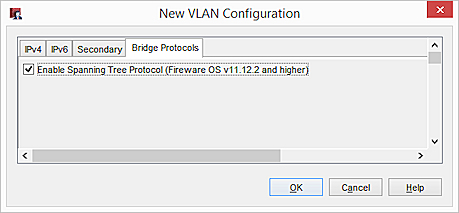
- Click Save.
You can now take the next step, and Assign Interfaces to a VLAN.
Before you can save this VLAN, you must Assign Interfaces to a VLAN.