
Related Topics
Configure FireCluster Manually
You can enable FireCluster manually or use the FireCluster Setup Wizard. For information about how to use the FireCluster Setup Wizard, see Use the FireCluster Setup Wizard .
Before you enable FireCluster:
- Make sure you have everything necessary to configure your FireCluster and that you have planned your configuration settings.
For information, see Before You Begin. - Make sure you understand the limitations of a FireCluster, as described in Features Not Supported for a FireCluster.
- Connect the FireCluster members to each other and to the network, as described in Connect the FireCluster Hardware.
- Make sure you understand how to configure a FireCluster with Firebox M5600 and M4600 models.
For information, see About FireCluster with Modular Interfaces - Make sure you understand how to set up an active/passive FireCluster with FireboxV or XTMv devices.
For information, see Configure a FireCluster on VMware ESXi.
In an active/active FireCluster configuration, the network interfaces for the cluster have multicast MAC addresses. Before you enable an active/active FireCluster, make sure your network routers and other devices are configured to support multicast network traffic. For more information, see Switch and Router Requirements for an Active/Active FireCluster.
Enable FireCluster
- In WatchGuard System Manager, connect to the Firebox that has the configuration you want to use for the cluster. This device becomes the cluster master the first time you save the configuration with FireCluster enabled.
- Click
 .
.
Or, select Tools > Policy Manager.
Policy Manager appears. - Select FireCluster > Configure.
The FireCluster Cluster Configuration dialog box appears.
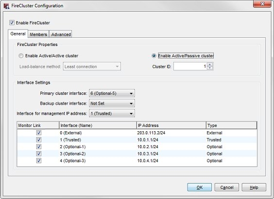
- Select the Enable FireCluster check box.
- Select which type of cluster you want to enable.
Enable Active/Passive cluster
Enables the cluster for high availability, but not load sharing. If you select this option, the cluster has an active member that handles all the network traffic and a passive member that handles traffic only if a failover of the other member occurs.
Enable Active/Active cluster
Enables the cluster for high availability and load sharing. If you select this option, the cluster balances traffic load across both cluster members.
- If you selected Enable Active/Active cluster, from the Load-balance method drop-down list, select the method to use to balance the traffic load between active cluster members.
Least connection
If you select this option, each new connection is assigned to the active cluster member that has the lowest number of open connections.
Round-robin
If you select this option, connections are distributed among the active cluster members in round-robin order. The first connection goes to one cluster member. The next connection goes to the other cluster member, and so on.
- From the Cluster ID drop-down list, select a number to identify this FireCluster.
The cluster ID uniquely identifies this FireCluster if there is more than one FireCluster active on the same layer 2 broadcast domain. If you only have one cluster, and your network does not have HSRP or VRRP devices, you can use the default value.
For an active/passive cluster, the Cluster ID determines the virtual MAC addresses used by the interfaces of the clustered devices. If you configure more than one active/passive FireCluster on the same subnet, it is important to know how to set the Cluster ID to avoid a possible virtual MAC address conflict. It is also possible that the FireCluster virtual MAC addresses can conflict with HSRP and VRRP configured devices on your network.
For more information, see Active/Passive Cluster ID and the Virtual MAC Address.
Configure Interface Settings
The cluster interface is the dedicated interface the cluster members use to communicate with each other about system status. You can configure either one or two cluster interfaces. For redundancy, if you have the interfaces available, we recommend you configure two cluster interfaces on each member—one primary, and one backup.
We recommend a direct cable connection:
- One cable between the primary cluster interfaces on each member
- Another cable between the backup cluster interfaces on each member
The primary and backup cluster interfaces must be on different subnets. If you use a switch between each member for the cluster interfaces, the cluster interfaces must be logically separated from each other on different VLANs.
You must disable any interfaces that are not connected to your network before you save the FireCluster configuration to the Firebox.
- From the Primary cluster interface drop-down list, select an interface to use as the primary interface.
- To use a second cluster interface, from the Backup cluster interface drop-down list, select an interface to use as the backup interface.
- Select an Interface for management IP address. This is the Firebox network interface you use to make a direct connection to a cluster device with any WatchGuard management application. You cannot select an external interface that uses PPPoE as the Interface for Management IP address. We recommend that you select the interface that the management computer usually connects to.
For more information, see About FireCluster Management IP Addresses. - Review the list of monitored interfaces. The list of monitored interfaces does not include the interfaces you configured as the primary and backup cluster interfaces. By default, FireCluster monitors the link status for all enabled interfaces. If the cluster master detects a loss of link on a monitored interface, the cluster master starts failover.
- For an active/passive cluster, you can select which of the active interfaces to monitor. If you do not want to monitor the link status of an enabled interface as a criteria for failover, clear the check box for that interface in the Monitor Link column.
We recommend that you configure the FireCluster to monitor the link status of all enabled interfaces.
An active/active FireCluster always monitors the link status of all enabled network interfaces. For an Active/Active FireCluster, you must disable any interface that is not connected to a network switch.
To disable an interface:
- In Policy Manager, select Network > Configuration.
- Double-click the interface that you want to disable.
- Set the Interface Type to Disabled.
If you enable a physical interface or add a Link Aggregation interface after FireCluster is enabled, that interface is automatically selected as a monitored interface in the FireCluster configuration.
Configure FireCluster Members
- Select the Members tab.
The FireCluster members configuration settings appear.
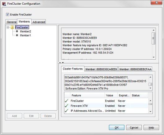
If you previously imported a feature key in this configuration file, that device is automatically configured as Member 1.
If you do not have a feature key in this configuration file, a FireCluster member does not appear in the list. In this case, you must add each device as a member and import the configuration file for each device, as described in the next steps.
- To add a member, click Add.
The Add member dialog appears.
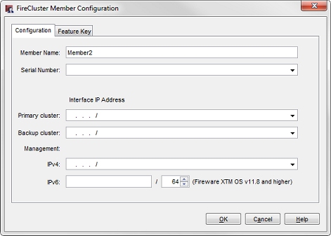
- In the Member Name text box, type a name. This name identifies this device in the members list.
- Select the Feature Key tab.
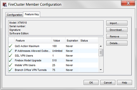
- Click Import.
The Import Firebox Feature Key dialog box appears. - To find the feature key file, click Browse.
Or, copy the text of the feature key file and click Paste to insert it in the dialog box. - Click OK.
- Select the Configuration tab.
The Serial Number field is automatically filled with the serial number from the feature key. - In the Interface IP Address section, type the addresses to use for each cluster interface and the interface for management IP address.
- In the Primary cluster text box, type the IP address to use for the primary cluster interface. The IP address for the primary cluster interface must be on the same subnet for each cluster member. The cluster member that has the highest IP address assigned to the primary cluster interface becomes the master if both devices start at the same time.
- In the Backup cluster text box, type the IP address to use for the backup cluster interface. This option only appears if you configured a backup cluster interface. The IP address for the backup cluster interface must be on the same subnet for each cluster member.
The primary and backup cluster interfaces must be on different subnets. If you use a switch between each member for the cluster interfaces, the cluster interfaces must be logically separated from each other on different VLANs.
- In the Management section, in the IPv4 text box, type the IP address to use to connect to an individual cluster member for maintenance operations. The interface for management is not a dedicated interface. It also is used for other network traffic. You must specify a different management IP address for each cluster member. The IPv4 management IP address must be an unused IP address. We recommend that you use an IP address on the same subnet as the IPv4 address assigned to the interface. It must also be on the same subnet as the WatchGuard Log Server or syslog server that your FireCluster sends log messages to.
- If the interface that you selected as the Interface for management IP address has IPv6 enabled, you can also configure an IPv6 management IP address. In the Management section, in the IPv6 text box, type the IPv6 address to use to connect to an individual cluster member for maintenance operations. The IPv6 management IP address must be an unused IP address. We recommend that you use an IP address that has the same prefix as an IPv6 IP address assigned to the interface.
For more information, see About FireCluster Management IP Addresses.
Do not set the Primary or Backup cluster IP address to the default IP address of any interface on the device. The default interface IP addresses are in the range 10.0.0.1–10.0.26.1. The Primary and Backup cluster IP addresses must not be used for anything else on your network, such as virtual IP addresses for Mobile VPN or the IP addresses used by remote branch office networks.
- Click OK.
The device you added appears on the Members tab as a cluster member. - Repeat the previous steps to add the second device to the cluster configuration.
If you want the second device to be automatically discovered and added to the cluster, do not save the configuration to the device until you start the second device with factory-default settings.
- Start the second device with factory-default settings.
For any Firebox model, or an XTM 33, 25, or 26 device, reset the device to factory-default settings
Use the reset instructions for your Firebox model. For more information, see Reset a Firebox.
For any XTM device with an LCD screen, start the device in safe mode
To start in safe mode, press and hold the down arrow button on the device front panel while you power on the device. Continue to hold the down arrow button until Safe Mode Starting... appears on the LCD display. When the device is in safe mode, the model number followed by the word safe appears on the LCD display.
- Save the configuration file to the cluster master.
The cluster is built. The cluster master automatically discovers the other device with the serial number that matches the serial number in the feature key you added to the cluster configuration
After the cluster is active, you can monitor the status of the cluster members on the Firebox System Manager Front Panel tab.
For more information, see Monitor and Control FireCluster Members.
If you save the configuration to the cluster master before you start the second device in safe mode, the cluster master does not automatically discover the second device. If the second device is not automatically discovered, you can use Firebox System Manager to manually trigger device discovery as described in Discover a Cluster Member.