
Related Topics
Set up a VPN from a Firebox to a Fortinet FortiGate Device
A branch office virtual private network (BOVPN) tunnel is a secure way for networks, or for a host and a network, to exchange data across the Internet. This topic tells you how to define a manual BOVPN tunnel between a WatchGuard Firebox and a Fortinet FortiGate (OS v4.0) device. Before you create a BOVPN tunnel, you must collect the IP addresses from each endpoint and agree on the common tunnel settings to use.
This topic does not give detailed information about the different BOVPN settings or how they affect an existing tunnel. If you want to know more about a particular setting, see:
To configure a VPN from a Firebox Cloud instance to a Fortinet FortiGate device, see Configure a VPN between Firebox Cloud and a FortiNet FortiGate device in the WatchGuard Knowledge Base.
WatchGuard provides interoperability instructions to help our customers configure WatchGuard products to work with products created by other organizations. If you need more information or technical support about configuring a non-WatchGuard product, see the documentation and support resources for that product.
VPN Configuration Summary
For reference purposes, here is a summary of the VPN configuration defaults for the Fortinet FortiGate device, with emphasis on any settings that do not match the default VPN configuration settings in Fireware v11.12.4.
In Fireware v12.0 and higher, the default BOVPN security settings are different. To determine whether those settings are compatible with your Fortinet device, see the documentation for your Fortinet device.
| VPN Settings | WatchGuard Device Default (v11.12.4) | Fortinet Device Default (OS v4.0) | Matched? |
|---|---|---|---|
| Phase 1 Settings | |||
| IKE Exchange Mode | Main | Main | Y |
| Authentication | SHA1 | SHA1 | Y |
| Encryption | 3DES | 3DES* |
Y |
| Diffie-Hellman Group | 2 | 5 | N |
| Phase 2 Settings | |||
| Perfect Forward Secrecy | No | Yes (DH5) | N |
| Protocol | ESP | ESP | Y |
| Authentication | SHA1 | SHA1 | Y |
| Encryption | AES (256-bit) | AES (128-bit)* | N |
WatchGuard and Fortinet devices have different default settings for Phase 1 and 2 encryption. For the VPN tunnel to build successfully, you must specify the same Phase 1 and 2 settings on your Firebox and Fortinet devices. For the strongest security, we recommend that you specify an AES variant for encryption.
Collect IP Address and Tunnel Settings
Before you can configure a branch office VPN, you must collect the public IP addresses of each device, and the IP addresses of the private networks you want to connect. You must also agree upon Phase 1 and Phase 2 settings to use for the VPN. This procedure describes how to configure a Firebox with the Phase 1 and Phase 2 settings that match the default settings on a Fortinet device.
For example, the IP address settings you collect could look like this:
WatchGuard Firebox:
External interface IP address: 203.0.113.2
Trusted network IP address: 10.0.1.0/24
Fortinet device:
External interface IP address: 198.51.100.2
Private network IP address: 10.50.1.0/24
Configure the Firebox
On the Firebox, you must add a VPN Gateway, and add a VPN tunnel that uses that gateway. The Phase 1 settings on the Firebox must match the Phase 1 settings on the Fortinet device.
Add the VPN Gateway
First you must add a gateway and configure the Phase 1 settings.

- Select VPN > Branch Office VPN.
- Below the Gateways list, click Add.
The Gateway settings page appears. - In the Gateway Name text box, type a name to identify this gateway.
- Select Use Pre-Shared Key. Type the shared key.
The shared key must use only standard ASCII characters. It must match the key used on the FortiGate device. - In the Gateway Endpoints section, click Add.
The Gateway Endpoints Settings dialog box appears.
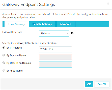
- From the External Interface drop-down list, select the external interface that has the public IP address.
- Select By IP Address. Type the external (public) IP address for the Firebox.
- Select the Remote Gateway tab.
- In the Specify the remote gateway IP address for a tunnel section, select Static IP Address. Type the external (public) IP address of the FortiGate device.
- In the Specify the gateway ID for tunnel authentication section, select By IP Address. Type the public IP address of the FortiGate device.
- Click OK to close the Gateway Endpoints Settings dialog box.
The gateway pair you defined appears in the Gateway Endpoints list. - Select the Phase 1 Settings tab.
- In the Transform Settings list, select the default Phase 1 Transform. Click Edit.
The Transform Settings dialog box appears.
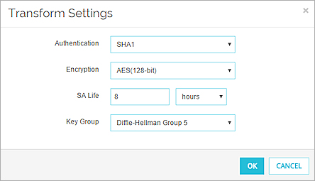
- From the Encryption drop-down list, select AES (128-bit) .
- From the Key Group drop-down list, select Diffie-Hellman Group 5.
This matches the default key group on the FortiGate device. - Click OK to close the Transform Settings dialog box.
- Click Save.
- Select VPN > Branch Office Gateways.
Click Add.
The New Gateway dialog box appears. - In the Gateway Name text box, type a name to identify this gateway in Policy Manager.
- Select Use Pre-Shared Key. Type the shared key.
The shared key must use only standard ASCII characters. It must match the key used on the FortiGate device. - In the Gateway Endpoints section, click Add.
The New Gateway Endpoints Settings dialog box appears.
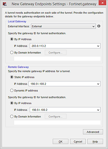
- From the External Interface drop-down list, select the external interface of the Firebox that has the public IP address.
- Select By IP Address.
- In the IP Address drop-down list, select the external (public) IP address for the Firebox.
- In the Specify the remote gateway IP address for a tunnel section, select Static IP Address. Type the external (public) IP address of the FortiGate device.
- In the Specify the gateway ID for tunnel authentication section, select By IP Address. Type the public IP address of the FortiGate device.
- Click OK to close the New Gateway Endpoints Settings dialog box.
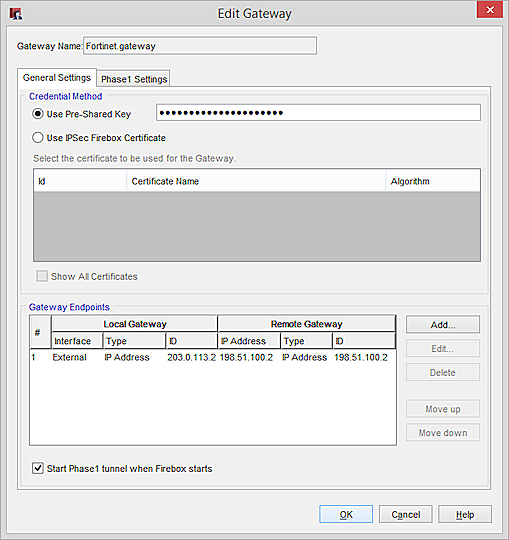
- Select the Phase 1 Settings tab.
- In the Transform Settings list, select the default Phase 1 Transform. Click Edit.
The Phase 1 Transform dialog box appears. - From the Encryption drop-down list, select AES (128-bit).
- From the Key Group drop-down list, select Diffie-Hellman Group5
This matches the default key group on the FortiGate device.
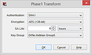
- Click OK to confirm the change to the Phase 1 Transform.
- Click OK to add the new gateway.
- Click OK to close the Gateways dialog box.
Add the VPN Tunnel
After you define the gateway, you can add a tunnel and configure the Phase 2 settings.
Create a Phase 2 proposal with settings that match the default Phase 2 settings on the Fortinet device:
- Select VPN > Phase2 Proposals.
- Click Add.
The Add Phase2 Proposal dialog appears.
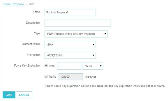
- In the Name field, type a meaningful name for the new proposal.
- From the Encryption drop-down list, select AES (128-bit).
- Click OK to save the new proposal.
Create a VPN tunnel that uses the new Phase 2 proposal and the gateway you added.
- Select VPN > Branch Office VPN.
- Below the Tunnels list, click Add.
The Tunnel page appears. - In the Name text box, type a meaningful name for this tunnel.
- From the Gateway drop-down list, select the gateway you configured to the Fortinet device.
- In the Addresses tab, click Add to add a tunnel route.
The Tunnel Route Settings dialog box appears.

- In the Local IP settings, from the Choose Type drop-down list, select Network IPv4. In the Network IP text box, type the network IP address for the local network that you want to use the VPN tunnel.
- In the Remote IP settings, select Network IPv4. In the Network IP text box, type the subnet IP address for the remote network on the FortiGate device that you want to use the VPN tunnel.
- Click OK to add the tunnel route.
The tunnel route is added to the Addresses tab of the Tunnel page. - Select the Phase 2 Settings tab.
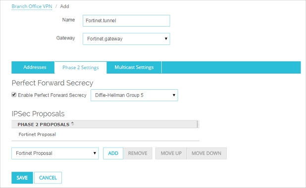
- Select the Enable Perfect Forward Secrecy check box.
- From the Enable Perfect Forward Secrecy drop-down list, select Diffie-Hellman Group 5.
This matches the default Diffie-Hellman group for PFS on the FortiGate device. - In the IPSec Proposals list, select the default ESP-AES-SHA1 proposal. Click Remove.
- From the IPSec Proposals drop-down list, select the new Phase 2 proposal you created earlier. Click Add.
- Click Save.
- Select VPN > Branch Office Tunnels.
The Branch Office IPSec Tunnels dialog box appears. - Click Add.
The New Tunnel dialog box appears. - In the Tunnel Name text box, type a meaningful name for this tunnel.
- From the Gateway drop-down list, select the gateway you configured to the Fortinet device.
- Click Add to add a tunnel route.
The Tunnel Route Settings dialog box appears.
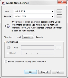
- In the Local text box, type subnet IP address for the local network on the Firebox that you want to use the VPN tunnel.
- In the Remote text box, type the subnet IP address for the remote network on the FortiGate device that you want to use the VPN tunnel.
- Click OK to add the tunnel route.
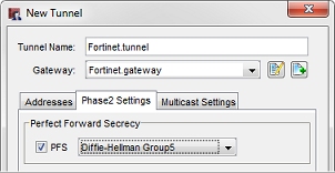
The tunnel route is added to the Addresses tab of the New Tunnel dialog box. - Select the Phase 2 Settings tab.
- Select the PFS check box. Select Diffie-Hellman Group5.
This matches the default Diffie-Hellman group on the FortiGate device.
- In the IPSec Proposals section, Select the default ESP-AES-SHA1 entry.
- Click Remove, and click OK to confirm that you want to remove the proposal.
- Click Add to add an IPSec Proposal.
- Select Create a new Phase2 proposal.
- In the Name text box, type a meaningful name for this proposal.
- From the Encryption drop-down list, select AES (128-bit).
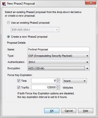
Leave all other settings at their default values.
- Click OK to add the New Phase2 Proposal.
- Click OK to add the new tunnel to the configuration.
- Click Close to close the Branch Office IPSec Tunnels dialog box.
- Save the configuration to the Firebox.
Configure the FortiGate device
This procedure describes how to manually configure the VPN settings for the Fortinet device.
Create address objects for the Fortinet and WatchGuard subnets.
The Fortinet device makes use of address objects for policy and VPN configuration. These address objects are similar to aliases on a Firebox.
- In the Fortinet web-based management interface, select Firewall Objects > Address > Address.
- Click Create New.
The New Address page appears.
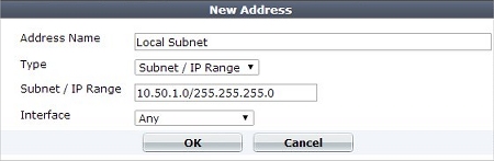
- In the Address Name text box, type a meaningful name for the local network.
- In the Subnet / IP Range text box, type the network IP and subnet mask for the local network.
- Click OK.
- Click Create New.
The New Address page appears.
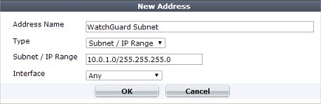
- In the Address Name text box, type a meaningful name for the remote network.
- In the Subnet / IP Range text box, type the network IP and subnet mask for the remote network.
- Click OK.
Create the Phase 1 Configuration
- In the Fortinet web-based management interface, select VPN > IPsec > Auto Key (IKE).
- Click Create Phase 1.
The New Phase 1 page appears.
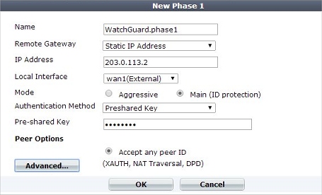
- In the Name text box, type a meaningful name for the VPN connection.
- In the IP Address text box, type the public IP address of the Firebox.
- From the Local Interface drop-down list, select the external interface which you want the VPN to use. By default, the local ID is the primary IP address for this interface.
- In the Pre-shared Key text box, type the same pre-shared key you chose for the Firebox VPN configuration.
- Click OK to confirm the Phase 1 configuration.
Create the Phase 2 Configuration
- In the Fortinet web-based management interface, select VPN > IPsec > Auto Key (IKE).
- Click Create Phase 2.
The New Phase 2 page appears.
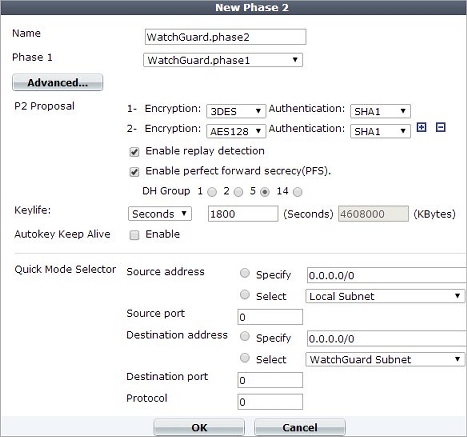
- In the Name text box, type a meaningful name for the Phase 2 VPN configuration.
- From the Phase 1 drop-down list, select the Phase 1 VPN configuration you created.
- Click Advanced.
All page content seen below the Advanced button appears. - Adjacent to Source Address in the Quick Mode Selector section, select the Select radio button.
- From the Select drop-down list, choose the address group you created for the local network.
- Adjacent to Destination Address in the Quick Mode Selector section, select the Select radio button.
- From the Select drop-down list, choose the address group you created for the remote network.
- Click OK to complete the phase 2 configuration.
Create a Policy to Allow VPN Traffic
You must create a policy on the Fortinet device to allow VPN traffic to pass.
- In the Fortinet web-based management interface, select Policy > Policy > Policy.
- Click Create New.
The New Policy page appears.
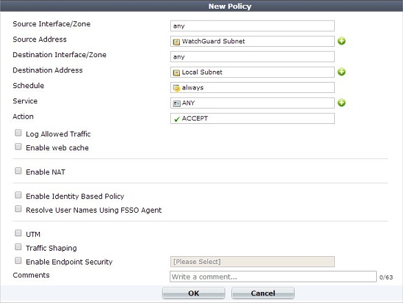
- Click the Source Interface/Zone text box and select the local interface used for the local network.
- Click the Source Address text box and select the address object you created for the local network.
- Click the Destination Interface/Zone text box and select the external interface which you chose for the VPN endpoint.
- Click the Destination Address text box and select the address object you created for the remote network.
- Click the Service text box and select ANY to allow any port and protocol to traverse the VPN tunnel.
- Click the Action text box, and select IPSEC.
The VPN Tunnel text box and associated options appear. - Click the VPN Tunnel text box, and select the Phase 1 configuration you created for this VPN.
- Confirm that Allow inbound and Allow outbound are selected.
After you complete the VPN configuration on the WatchGuard and Fortinet devices, a device on either network must send traffic to the remote network to initiate the VPN tunnel.
See Also
Troubleshoot Branch Office VPN Tunnels
Configure a VPN between Firebox Cloud and a FortiNet FortiGate device in the WatchGuard Knowledge Base