
Related Topics
VPN Modem Failover and Multi-WAN
You can use modem failover and multi-WAN failover together to provide increased redundancy for the branch office VPN connections between two networks. When you enable modem failover on a device, you can configure the branch office VPN gateway to use the modem for failover. If the device has multiple external interfaces, you must configure the branch office VPN gateway endpoint settings so that each interface uses a unique local ID for gateway authentication. The gateway configuration examples below show how to configure gateway endpoint settings for branch office VPN configurations between sites with or without multi-WAN enabled at each site.
This topic focuses on just the gateway endpoint settings. For a complete description of branch office VPN modem failover, see Configure VPN Modem Failover
In these examples, the branch office VPN is configured between Fireboxes at two sites, a central office and a small office. The small office uses a modem connection for failover. For these examples, the two devices use these IP addresses:
Central office — Firebox without modem failover
- External: 203.0.113.2/24
- External-2: 192.0.2.2/24 (only if multi-WAN is enabled)
Small office — Firebox with modem failover enabled
- External: 198.51.100.2/24
- External-2: dynamic IP address (only if multi-WAN is enabled)
- Modem failover is enabled and configured in Network > Modem
Example 1 — Single WAN at Both Sites
The Fireboxes at the small office and the central office each have one physical external interface. Modem failover is enabled at the small office. The gateway endpoints pair defined in the branch office VPN gateway configuration at each site must use the same ID to refer to the gateway endpoint at the small office.
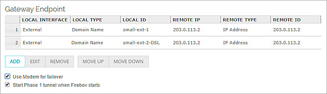
The gateway endpoint configuration at the small office:
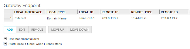
Gateway endpoint configuration on the Firebox at the small office, in Fireware Web UI
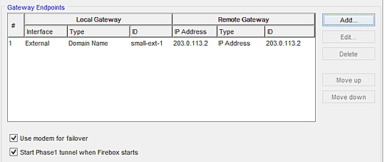
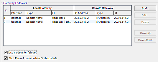
Gateway endpoint configuration on the Firebox at the small office, in Policy Manager
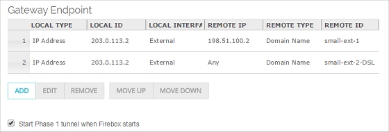
Gateway endpoint configuration at the central office:
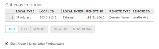
Gateway endpoint configuration on the Firebox at the central office, in Fireware Web UI
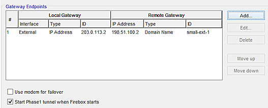
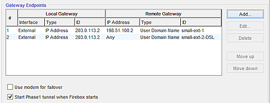
Gateway endpoint configuration on the Firebox at the central office, in Policy Manager
If the external interface at the small office is down, modem failover occurs. The Firebox at the small office uses the local ID to connect to the Firebox at the central office through the modem.
Example 2 — Multi-WAN at the Small Office
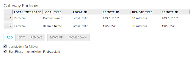
The Firebox at the central office has a single physical external interface. The Firebox at the small office has two physical external interfaces. Modem failover is enabled at the small office. The ID used to identify each interface at the small office must be different.
Gateway endpoint configuration on the Firebox at the small office:
Gateway endpoint configuration on the Firebox at the small office, in Fireware Web UI
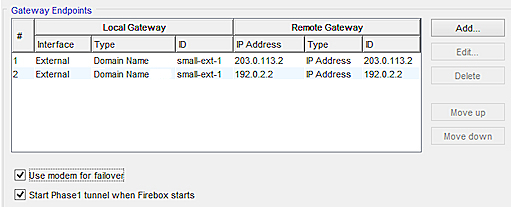
Gateway endpoint configuration on the Firebox at the small office, in Policy Manager
Gateway endpoint pairs on the Firebox at the central office:
Gateway endpoint configuration on the Firebox at the central office, in Fireware Web UI
Gateway endpoint configuration on the Firebox at the central office, in Policy Manager
If both external interfaces at the small office are down, modem failover occurs. The Firebox at the small office uses the first local ID to connect to the Firebox at the central office through the modem.
Example 3 — Multi-WAN at the Central Office
The Firebox at the central office has two physical external interface. The Firebox at the small office has one physical external interface. Each device has two gateway endpoint pairs.
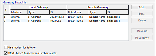
Gateway endpoint pairs on the Firebox at the small office:
Gateway endpoint pair configured on the Firebox at the small office, in Fireware Web UI
Gateway endpoint configuration on the Firebox at the small office, in Policy Manager
Gateway endpoint pairs on the Firebox at the central office:
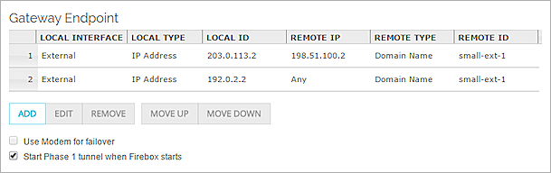
Gateway endpoint configuration on the Firebox at the central office, in Fireware Web UI
Gateway endpoint configuration on the Firebox at the central office, in Policy Manager
If the external interface at the small office is down, modem failover occurs. The Firebox at the small office uses the local gateway ID to connect to the Firebox at the central office through the modem.
Multi-WAN at Both Sites
It is also possible to configure both sites to use multi-WAN, along with modem failover. In that case, you configure four gateway endpoint pairs on each device, just as you would if modem failover was not enabled. The only difference is that for modem failover, you must use a local ID for authentication of the device that has modem failover enabled.