
Related Topics
Set up a VPN from a Firebox to a Cisco ISR Device
A branch office virtual private network (BOVPN) tunnel is a secure way for networks, or for a host and a network, to exchange data across the Internet. This document tells you how to define a manual BOVPN tunnel between a WatchGuard Firebox and a Cisco Integrated Services Router (877 DSL Modem in this example). The configuration assumes connectivity is already established between the external interfaces of each device. The Cisco device in this example is configured as a split tunnel.
WatchGuard provides interoperability instructions to help our customers configure WatchGuard products to work with products created by other organizations. If you need more information or technical support about configuring a non-WatchGuard product, see the documentation and support resources for that product.
Collect IP Address and Tunnel Settings
To create a manual BOVPN tunnel, the first thing you must do is collect the IP addresses and decide the settings that the endpoints will use.
In this example, the two devices use these network settings:
Firebox:
External interface IP address: 203.0.113.2
Trusted network IP address: 192.168.20.0/24
Cisco ISR device:
External interface IP address: 198.51.100.2
Private network IP address: 192.168.1.0/24

In this example, both endpoints have static external IP addresses. For information about branch office VPNs to a device that has a dynamic external IP address, see Define Gateway Endpoints for a BOVPN Gateway.
You also need to choose what Phase 1 and Phase 2 settings to use. In this example, we use the default Phase 1 and Phase 2 VPN configuration settings on a Firebox with Fireware v11.12.4. We then configure the VPN configuration settings on the Cisco ISR device to match the default settings on the Firebox.
Make sure that you configure the VPN endpoints correctly and that the Phase 1 and Phase 2 settings are the same on both devices. Tunnels cannot be created if the settings do not match.
In Fireware v12.0 and higher, the default BOVPN security settings are different. To determine whether those settings are compatible with your Cisco device, see the documentation for your Cisco device.
Configure the WatchGuard Device
On the Firebox, you must add a VPN gateway, and add a VPN tunnel that uses that gateway.
Add the VPN Gateway
- Select VPN > Branch Office VPN.
- In the Gateways section, click Add.
The Gateway settings page appears.
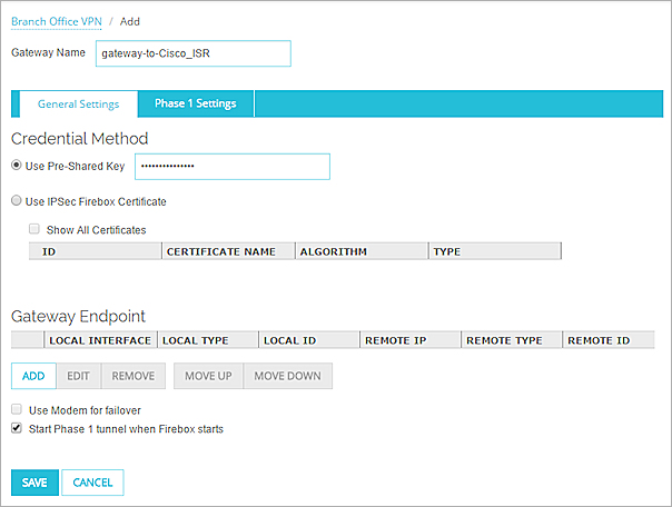
- In the Gateway Name text box, type a name to identify this gateway in Policy Manager.
- Type a Pre-Shared Key. You must use the same key when you configure the Cisco ISR device.
- In the Gateway Endpoints section, click Add.
The New Gateway Endpoints Settings dialog box appears.

- From the External Interface drop-down list, select the external interface to use.
- In the By IP Address text box, type the external IP address of the Firebox.
For this example, the local gateway IP address is 203.0.113.2. - Select the Remote Gateway tab.

- Type the external IP address of the Cisco ISR device in the two IP Address text boxes.
For this example, the remote gateway IP address is 198.51.100.2. - Click OK to add the gateway endpoint settings.
- Click Save to save the new gateway.
The new gateway appears in the Gateways list.
- Select VPN > Branch Office Gateways.
The Gateways dialog box appears. - Click Add.
The New Gateway dialog box appears.
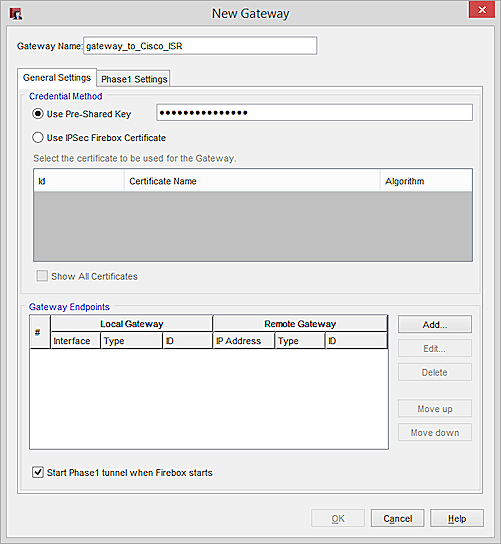
- In the Gateway Name text box, type a name to identify this gateway in Policy Manager.
- Type a Pre-Shared Key. You must use the same key when you configure the Cisco ISR device.
- In the Gateway Endpoints section, click Add.
The New Gateway Endpoints settings dialog box appears.

- In the Local Gateway section, from the External Interface drop-down list, select the external interface to use.
- In the By IP Address text box, type the external IP address of the Firebox.
For this example, the local gateway IP address is 203.0.113.2. - In the Remote Gateway section, type the external IP address of the Cisco ISR device in the two IP Address text boxes.
For this example, the remote gateway IP address is 198.51.100.2. - Click OK to add the gateway endpoint settings.
- Click OK to save the new gateway.
The new gateway appears in the Gateways dialog box. - Click Close to close the Gateways dialog box.
Add the Branch Office VPN Tunnel
- In the Tunnels section, click Add.
The Tunnel page appears.
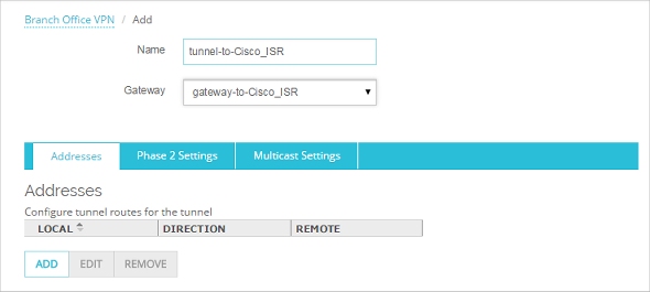
- In the Tunnel Name text box, type a name for the tunnel.
- From the Gateway drop-down list, select the gateway you just created.
- In the Addresses tab, click Add to add a new tunnel route.
The Tunnel Route Settings dialog box appears,

- To create a tunnel route between the private networks at each site:
- In the Local IP section, from the Choose Type drop-down list, select Network IPv4. In the Network IP text box, type the network IP address of the trusted network on the Firebox.
For this example, the local trusted network IP address is 192.168.20.0/24. - In the Remote IP section, from the Choose Type drop-down list, select Network IPv4. In the Network IP text box, type the network IP address of the private network on the Cisco ISR device.
For this example, the remote private network IP address is 192.168.1.0/24.
- Click OK to add the new tunnel route.
- Click Save to add the new tunnel.
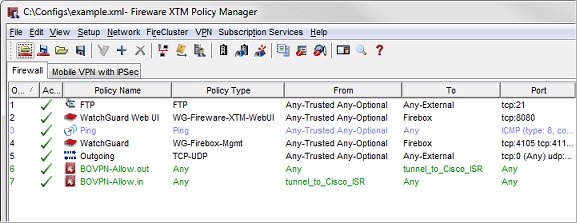
When you save the tunnel, Fireware automatically adds two new policies.
- The policy BOVPN-Allow.out allows traffic:
- From: Any
- To: tunnel-to-Cisco-ISR
- The policy BOVPN-Allow.in allows traffic:
- From: tunnel-to-Cisco-ISR
- To: Any
- Select VPN > Branch Office Tunnels.
- Click Add.
The New Tunnel dialog box appears.
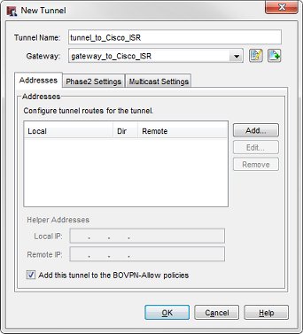
- In the Tunnel Name text box, type a name for the tunnel.
- From the Gateway drop-down list, select the gateway you just created.
- In the Addresses tab, click Add to add a new tunnel route.
The Tunnel Route Settings dialog box appears,

- To create a tunnel route between the private networks at each site:
- In the Local text box, type the network IP address of the trusted network on the Firebox.
For this example, the local trusted network IP address is 192.168.20.0/24. - In the Remote text box, type the network IP address of the private network on the Cisco ISR device.
For this example, the remote private network IP address is 192.168.1.0/24.
- Click OK to add the new tunnel route.
- Click OK to add the new tunnel.
The new tunnel appears in the Branch Office IPSec Tunnels dialog box. - Click Close to close the Branch Office IPSec Tunnels dialog box.
Policy Manager automatically adds two new policies, BOVPN-Allow.out, and BOVPN-Allow.in.
- Save the configuration to the Firebox.
Configure the Cisco ISR Device
Use these steps to set up the VPN gateway and tunnel on the Cisco ISR device.
- Log in to the Cisco CLI Enable Mode and enter configuration mode (conf t).
- If necessary, modify access-lists used for NAT, to prevent translation of VPN traffic:
Router(config)#ip access-list extended NAT_ACL
Router(config-ext-nacl)#deny ip 192.168.1.0 0.0.0.255 192.168.20.0 0.0.0.255
Router(config-ext-nacl)#permit ip 192.168.1.0 0.0.0.255 any
Router(config-ext-nacl)#end
Router#conf t
Router(config)#ip nat inside source list NAT_ACL interface Dialer0 overload (replace Dialer0 with the interface connected to the Internet)
- Configure Phase 1 settings.
Router(config)#crypto isakmp policy 1
Router(config-isakmp)#encryption 3des
Router(config-isakmp)#group 2
Router(config-isakmp)#hash sha
Router(config-isakmp)#authentication pre-share
Router(config-isakmp)#end
Router#conf t
Router(config)#crypto isakmp key 0 Password1! address 203.0.113.2
- Configure Phase 2 settings.
Router(config)#crypto ipsec transform-set vpn esp-aes 256 esp-sha-hmac
Router(config)#crypto map towatchguard 1 ipsec-isakmp
Router(config-crypto-map)#description tunnel_to_watchguard
Router(config-crypto-map)#set peer 203.0.113.2
Router(config-crypto-map)#set security-association lifetime kilobytes 1280000
Router(config-crypto-map)#set security-association lifetime seconds 86400
Router(config-crypto-map)#set transform-set vpn
Router(config-crypto-map)#match address 100 (remember to create access-list 100)
Router(config-crypto-map)#reverse-route
- Add the access list 100:
Router(config)#access-list 100 permit ip 192.168.1.0 0.0.0.255 192.168.20.0 0.0.0.255
- Add the VPN to the interface:
Router(config)#interface Dialer0 (replace Dialer0 with the interface connected to the Internet)
Router(config-if)#crypto map vpn
- Save the configuration to the Cisco (write mem)
Troubleshoot the VPN Tunnel
To troubleshoot VPN connectivity from the Cisco device, use these commands in the Cisco CLI:
Router#clear crypto sessions (Resets the SA manually)
Router#debug crypto isakmp
Router#debug crypto ipsec
To troubleshoot the VPN tunnel from the Firebox, you can run the VPN Diagnostic Report.
For more information, see Use the VPN Diagnostic Report