
Related Topics
Set up a VPN from a Firebox to a Cisco ASA Device
A branch office virtual private network (BOVPN) tunnel is a secure way for networks, or for a host and a network, to exchange data across the Internet. This document tells you how to define a manual BOVPN tunnel between a Firebox and a Cisco ASA (8.6(1)2) device. Before you create a BOVPN tunnel, you must collect the IP addresses from each endpoint and agree on the common tunnel settings to use.
This topic does not give detailed information on what the different BOVPN settings mean, or the effects those settings can have on the tunnel that is built. If you want to know more about a particular setting, use these resources:
WatchGuard provides interoperability instructions to help our customers configure WatchGuard products to work with products created by other organizations. If you need more information or technical support about configuring a non-WatchGuard product, see the documentation and support resources for that product.
VPN Configuration Summary
For reference purposes, here is a summary of the VPN configuration defaults for the Cisco ASA device, with emphasis on any settings that do not match the default VPN configuration settings in Fireware v11.12.4.
In Fireware v12.0 and higher, the default BOVPN security settings are different. To determine whether those settings are compatible with your Cisco device, see the documentation for your Cisco device.
| VPN Settings | WatchGuard Device Default (v11.12.4) | Cisco ASA Device Default (8.6(1)2) | Matched? |
|---|---|---|---|
| Phase 1 Settings | |||
| IKE Exchange Mode | Main | Main + IKEv2 | N |
| Authentication | SHA1 | * See below | Y |
| Encryption | 3DES | * See below | Y |
| Diffie-Hellman Group | 2 | 2 | Y |
| Phase 2 Settings | |||
| Perfect Forward Secrecy | No | Yes | N |
| Protocol | ESP | ESP | Y |
| Authentication | SHA1 | * See below | Y |
| Encryption | AES (256-bit) | * See below | N |
* For both Phase 1 and Phase 2, the Cisco ASA has a wide variety of proposals. The default settings for your Firebox will match one of the proposals, but if you do not remove the other proposals from the Cisco configuration the Firebox might create log messages during VPN negotiations that indicate failure, even when the VPN is successfully established.
In most VPN configurations, you can leave the tunnel timeout values for Phase 1 and 2 at their default values, as long as all other settings match. In some cases, VPN negotiations with Cisco ASA devices will fail when the Firebox is the initiator. For this reason, you might want to set the timeout value in the Cisco ASA VPN configuration to a lower value than the default timeout on the Firebox.
Collect IP Address and Tunnel Settings
To create a manual BOVPN tunnel, the first thing you must do is collect the IP addresses and decide the settings that the endpoints will use.
Before you can configure a branch office VPN, you must collect the public IP addresses of each device, and the IP addresses of the private networks you want to connect. You must also choose the Phase 1 and Phase 2 settings to use for the VPN. This procedure describes how to configure a Firebox with the Phase 1 and Phase 2 settings that match the default settings on a Cisco device.
For example, the IP address settings you collect could look like this:
WatchGuard Firebox:
External interface IP address: 203.0.113.2
Trusted network IP address: 10.0.1.0/24
Cisco ASA device:
External interface IP address: 198.51.100.2
Private network IP address: 10.50.1.0/24
Configure the WatchGuard Device
On the Firebox you add a VPN gateway, and add a VPN tunnel that uses that gateway.
Add the VPN Gateway
- Select VPN > Branch Office VPN.
- Below the Gateways list, click Add.
The Gateway settings page appears. - Select Use Pre-Shared Key. Type the shared key.
The shared key must use only standard ASCII characters. It must match the key used on the Cisco device. - Below the Gateway Endpoint list, click Add.
The Gateway Endpoint Settings dialog box appears.

- From the External Interface drop-down list, select the external interface that has the public IP address.
- Select By IP Address. Type the external (public) IP address for the Firebox.
- Select the Remote Gateway tab.
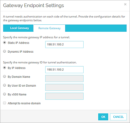
- In the Specify the remote gateway IP address for a tunnel section, select Static IP Address. Type the external (public) IP address of the Cisco device.
- In the Specify the gateway ID for tunnel authentication section, select By IP Address. Type the public IP address of the Cisco device.
- Click OK to close the Gateway Endpoint Settings dialog box.
The gateway pair you defined appears in the list of gateway endpoints.
- In Policy Manager, select VPN > Branch Office Gateways.
- Click Add.
The New Gateway dialog box appears. - In the Gateway Name text box, type a name to identify this gateway in Policy Manager.
- Select Use Pre-Shared Key. Type the shared key.
The shared key must use only standard ASCII characters. It must match the key used on the Cisco device. - In the Gateway Endpoints section, click Add.
The New Gateway Endpoints settings dialog box appears.
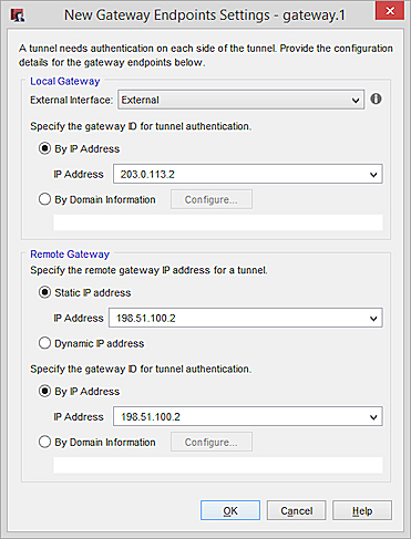
- From the External Interface drop-down list, select the external interface that has the public IP address.
- In the Local Gateway section, select By IP Address.
- From the IP Address drop-down list, select the external (public) IP address for the device.
- In the Specify the remote gateway IP address for a tunnel section, select Static IP Address. Type the external (public) IP address of the Cisco device.
- In the Specify the gateway ID for tunnel authentication section, select By IP Address. Type the public IP address of the Cisco device.
- Click OK.
The gateway endpoint pair you defined appears in the list of gateway endpoints. - Click OK to add the gateway.
- Click Close.
Add the VPN Tunnel
- Select VPN > Branch Office.
- Below the Tunnels list, click Add.
- In the Name text box, type a meaningful name for this tunnel.
- From the Gateway drop-down list, select the gateway you configured to the Cisco device.
- Below the Addresses list, click Add.
The Tunnel Route Settings dialog box appears.
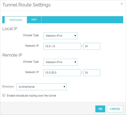
- In the Local IP settings, from the Choose Type drop-down list, select Network IPv4. Type the network IP address for the local network that you want to use the VPN tunnel.
- In the Remote IP settings, from the from the Choose Type drop-down list, select Network IPv4. Type the network IP address for the private network on the Cisco device that you want to use the VPN tunnel.
- Click OK to add the tunnel route.
The tunnel route is added to the Addresses tab of the tunnel configuration. - Click Save.
The tunnel route configuration is added to the Tunnels list.
- In Policy Manager, select VPN > Branch Office Tunnels.
The Branch Office IPSec Tunnels dialog box appears. - Click Add.
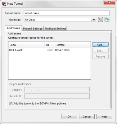
The New Tunnel dialog box appears. - In the Tunnel Name text box, type a meaningful name for this tunnel.
- From the Gateway drop-down list, select the gateway you configured to the Cisco device.
- Click Add to add a tunnel route.
The Tunnel Route Settings dialog box appears. - In the Local text box, type the network IP address for the local network that you want to use the VPN tunnel.
- In the Remote text box, type the network IP address for the private network on the Cisco device that you want to use the VPN tunnel.
- Click OK to add the tunnel route.
The tunnel route is added to the Addresses tab of the New Tunnel dialog box.
- Click OK to add the new tunnel to the configuration.
- Click Close to close the Branch Office IPSec Tunnels dialog box.
- Select File > Save > To Firebox to save the configuration to your device.
Configure the Cisco ASA Device
This procedure describes how to manually configure the VPN settings for the Cisco ASA device in the ASDM interface. If you prefer the terminal interface for this device, please consult Cisco product documentation for assistance.
Create Address Objects for the Cisco and WatchGuard Subnets
The Cisco device makes use of address objects for policy and VPN configuration. These address objects are very similar to aliases on a Firebox.
To create address objects in the configuration section of the ASDM interface:
- From the sidebar menu, select Firewall.
- In the Firewall menu, select Objects > Network Objects/Groups.
- Click Add > Network Object.
The Add Network Object dialog box appears.

- In the Name text box, type a meaningful name for the local network behind the Firebox.
- From the Type drop down list, select Network.
- In the IP Address text box, type the subnet ID for the local network connected to the Firebox.
- In the Netmask text box, type the subnet mask for the local network connected to the Firebox.
- Click OK to complete the Network Object configuration.
If you have not already configured a Network Object for the local network connected to the Cisco ASA device, repeat these steps to create one. Use the IP address and Netmask for the local network connected to the Cisco device.
Configure a Connection Profile
In the configuration section of the ASDM interface:
- From the sidebar menu, select Site-to-Site VPN.
- Under Connection Profiles, click Add.
The Add IPsec Site-to-Site Connection Profile dialog box appears.
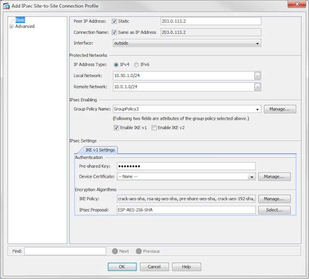
- In the Peer IP Address text box, type the public IP address of the external interface on the Firebox.
- From the Interface drop down list, select the external interface the VPN tunnel will use on the Cisco device.
- In the Local Network text box, type the network IP address of the network behind the Cisco device, or click the adjacent button to select the network object you defined for the local network.
- In the Remote Network text box, type the network IP address of the network behind the Firebox, or click the adjacent button to select the network object you defined for the WatchGuard network.
- Clear the Enable IKE v2 check box.
- In the Pre-shared key text box in the IKE v1 Settings tab of the IPsec Settings section, type the pre-shared key you configured for this gateway on the Firebox.
- In the IPsec Proposal text box, remove every entry except ESP-AES-256-SHA. This reduces the number of VPN error messages that appear in the Firebox log file.
- Click OK to complete the VPN configuration.
If you want to make any changes to the Advanced settings for this connection profile, click OK and then re-open the profile. Some options in the Basic section revert to their default settings if you edit the Advanced settings before you save the connection profile.
- Click Apply to save the changes to your running configuration.
Changes you make to the running configuration do not persist through a reboot of the Cisco device. To commit these changes to the permanent flash memory, click the Save icon at the top of the ASDM interface.
After you complete the VPN configuration on the WatchGuard and Cisco devices, a host in either network must send traffic to the remote network to initiate VPN tunnel negotiations.