Configure One VLAN Bridged Across Two Interfaces
You can configure a VLAN to bridge across two interfaces of the Firebox. You might want to bridge one VLAN across two interfaces if your organization is spread across multiple locations. For example, suppose your network is on the first and second floors in the same building. Some of the computers on the first floor are in the same functional group as some of the computers on the second floor. You want to group these computers into one broadcast domain so that they can easily share resources, such as a dedicated file server for their LAN, host-based shared files, printers, and other network accessories.
This example shows how to connect two 802.1Q switches so that both switches can send traffic from the same VLAN to two interfaces on the same Firebox.

In this example, two 802.1Q switches are connected to Firebox interfaces 3 and 4, and carry traffic from the same VLAN.
Define the VLAN on the Firebox
On the Firebox, configure VLAN 10 to handle tagged VLAN traffic from interfaces 3 and 4.
- Select Network > Configuration.
- Select the VLAN tab.
- Click Add.
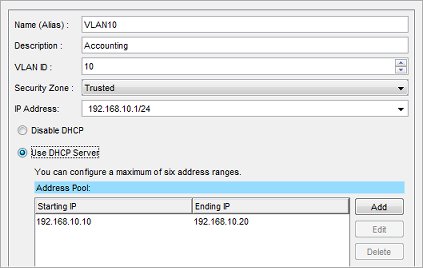
The New VLAN Configuration dialog box appears. - In the Name (Alias) text box, type a name for the VLAN. For this example, type VLAN10.
- In the Description text box, type a description. For this example, type Accounting.
- In the VLAN ID text box, type the VLAN number configured for the VLAN on the switch. For this example, type 10.
- From the Security Zone drop-down list, select the security zone. For this example, select Trusted.
- In the IP Address text box, type the IP address to use for the Firebox on this VLAN. For this example, type 192.168.10.1/24.
Any computer in this new VLAN must use this IP address as its default gateway.
- (Optional) To configure the Firebox to act as a DHCP server for the computers on VLAN10:
- Select Use DHCP Server.
- To the right of the Address Pool list, click Add.
- For this example, in the Starting address text box, type 192.168.10.10 and in the Ending address text box type 192.168.10.20.
The finished VLAN10 configuration for this example looks like this:
- Click OK to add the new VLAN.
- To make Firebox interfaces 3 and 4 members of the new VLAN, select the Interfaces tab.
- Select Interface 3. Click Configure.
The Interface Settings dialog box appears.
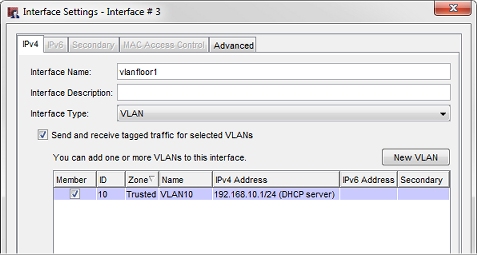
- From the Interface Type drop-down list, select VLAN.
- Select the Send and receive tagged traffic for selected VLANs check box.
- In the Member column, select the check box for VLAN10. Click OK.
- Select Interface 4. Click Configure.
The Interface Settings dialog box appears.
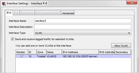
- From the Interface Type drop-down list, select VLAN.
- Select the Send and receive tagged traffic for selected VLANs check box.
- In the Member column, select the check box for VLAN10. Click OK.
- Select the VLAN tab.
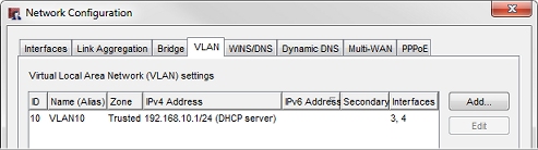
- Verify that Interfaces column for VLAN10 shows interfaces 3 and 4.
- Save the configuration to the device.
- Select Network > Interfaces.
- Select interface number 3. Click Edit.
- In the Interface Name (Alias) text box, type a name. For this example, typevlanfloor1.
- From the Interface Type drop-down list, select VLAN.
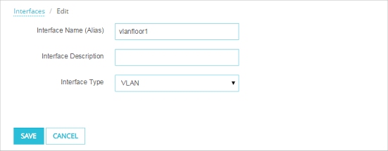
- Click Save.
- Repeat the same steps to configure Interface 4 as a VLAN interface called vlanfloor2.
- Select Network > VLAN.
- Click Add.
- In the Name text box, type a name for the VLAN. For this example, type VLAN10.
- In the Description text box, type a description. For this example, type Accounting.
- In the VLAN ID text box, type the VLAN number configured for the VLAN on the switch. For this example, type 10.
- From the Security Zone drop-down list, select the security zone. For this example, select Trusted.
- In the IP Address text box, type the IP address to use for the Firebox on this VLAN. For this example, type 192.168.10.1/24.
- In the list of interfaces, select both interfaces.
- From the Select Traffic drop-down list, select Tagged traffic.
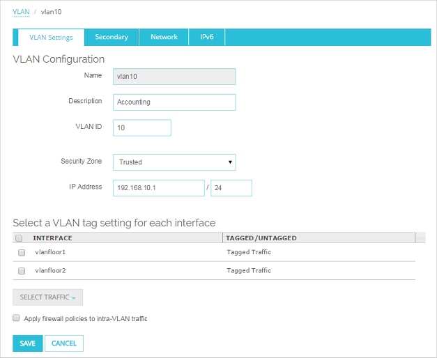
- Click Save.
To apply firewall policies to the traffic between the two networks that are part of this VLAN, select the Apply firewall policies to intra-VLAN traffic check box in the VLAN configuration. For more information, see Define a New VLAN.
Configure the Switches
Configure each of the switches that connect to interfaces 3 and 4 of the Firebox. Refer to the instructions from your switch manufacturer for details about how to configure your switches.
Configure the Switch Interfaces Connected to the Firebox
The physical segment between the switch interface and the Firebox interface is a tagged data segment. Traffic that flows over this segment must use 802.1Q VLAN tagging.
Some switch manufacturers refer to an interface configured in this way as a trunk port or a trunk interface.
On each switch, for the switch interface that connects to the Firebox:
- Disable Spanning Tree Protocol.
- Configure the interface to be a member of VLAN10.
- Configure the interface to send traffic with the VLAN10 tag.
- If necessary for your switch, set the switch mode to trunk.
- If necessary for your switch, set the encapsulation mode to 802.1Q.
Configure the Other Switch Interfaces
The physical segments between each of the other switch interfaces and the computers (or other networked devices) that connect to them are untagged data segments. Traffic that flows over these segments does not have VLAN tags.
On each switch, for the switch interfaces that connect computers to the switch:
- Configure these switch interfaces to be members of VLAN10.
- Configure these switch interfaces to send untagged traffic for VLAN10.
Physically Connect All Devices
- Use an Ethernet cable to connect Firebox interface 3 to the Switch A interface that you configured to tag for VLAN10 (the VLAN trunk interface of Switch A).
- Use an Ethernet cable to connect the Firebox interface 4 to the Switch B interface that you configured to tag for VLAN10 (the VLAN trunk interface of Switch B).
- Connect a computer to the interface on Switch A that you configured to send untagged traffic for VLAN10.
- Configure the network settings on the connected computer. The settings depend on whether you configured the Firebox to act as a DHCP server for the computers on VLAN10 in Step 9 of Define the VLAN on the Firebox.
- If you configured the Firebox to act as a DHCP server for the computers on VLAN10, configure the computer to use DHCP to get an IP address automatically. See Step 9 in the procedure Define the VLAN, above.
- If you did not configure the Firebox to act as a DHCP server for the computers on VLAN10, configure the computer with an IP address in the VLAN subnet 192.168.10.x. Use subnet mask 255.255.255.0 and set the default gateway on the computer to the Firebox VLAN IP address 192.168.10.1
- Repeat the previous two steps to connect a computer to Switch B.
Test the Connection
After you complete these steps, the computers connected to Switch A and Switch B can communicate as if they were connected to the same physical local area network. To test this connection you can:
- Ping from a computer connected to Switch A to a computer connected to Switch B.
- Ping from a computer connected to Switch B to a computer connected to Switch A.