At the upper-left corner of the window, Firebox System Manager (FSM) has a visual display that shows the direction of traffic for the Firebox interfaces. The display also shows whether the current traffic is allowed or denied at each interface. The display can be in the shape of a triangle or a star.
The points of the star and triangle show the traffic that flows through the interfaces. A green point shows traffic is allowed at that interface. A red point shows that either traffic is denied, or that some traffic is denied and other traffic is allowed. Each point shows incoming connections and outgoing connections with different arrows. When traffic flows between the two interfaces, the arrows light up in the direction of the traffic.
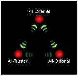
Triangle Display
In the triangle figure, the points of the triangle show the network traffic. The points show only the idle or deny condition. One exception is when there is a lot of default-route VPN traffic. Default-route VPN traffic refers to packets that are sent through a VPN to a Firebox configured as the default gateway for the VPN network. In this case, the FSM traffic level indicator can show very high traffic, but you do not see green lights when more default-route VPN traffic goes in and out of the same interface.
If a Firebox has only three configured interfaces, each corner of the triangle is one interface. If a device has more than three interfaces, each corner of the triangle represents one type of interface. For example, if you have six configured interfaces with one external, one trusted, and four optional interfaces, the All-Optional corner in the triangle represents all four of the optional interfaces.
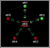
Star Display
In the star figure, the location where the points come together can show one of two conditions:
- Red (deny) — The Firebox denies a connection on that interface.
- Green (allow) — There is traffic between this interface and a different interface (but not the center) of the star. When there is traffic between this interface and the center, the point between these interfaces appears as green arrows that blink.
The star display shows all traffic in and out of the center interface. An arrow moves from the center interface to a node interface to show the flow of traffic through the Firebox. The traffic comes in through the center interface and goes out through the node interface. For example, if eth1 is at the center and eth2 is at a node, a green arrow shows that traffic flows from eth1 to eth2.
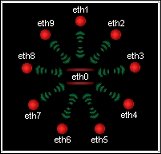
The star display looks different depending on the type of connected Firebox. The number of nodes in the star changes to match the number of interfaces on your device. One interface is located in the center of the star, and then each additional interface appears on a node of the star. For example, if your device has 6 interfaces, the star has 5 nodes, and if your device has 10 interfaces, the star has 9 nodes.
If you use the star figure, you can customize the interface that appears in its center.
To customize the interface:
Click the interface name or its point.
The interface moves to the center of the star. All the other interfaces move clockwise.
If you move an interface to the center of the star, you can see all traffic between that interface and all other interfaces. The default display shows the external interface in the center.
To change the display:
Right-click inside the display area and select Triangle Mode or Star Mode.