There are several reasons to use publicly routable IP addresses on a network protected by your Firebox. For example, you might want to avoid the use of NAT to translate a public IP address to a private IP address for publicly accessible servers on your network. You might want to use a service that does not work well with NAT. Or, you might want to use multi-WAN on the Firebox to create redundant paths to the public IP addresses of servers on your network.
The objective of this configuration example is to show how an organization could configure public subnets on the private network behind the Firebox.
Solution Overview
In this configuration example, we created a configuration file for each scenario:
- Scenario 1 — Public subnet behind the Firebox - single WAN, /24 subnet
- Scenario 2 — Public subnet behind the Firebox - single WAN, /24 supernet with two /25 subnets
- Scenario 3 — Public subnet behind the Firebox with multi-WAN
In general, these solutions require that you:
- Add a static route to the Internet router so that it can route traffic to the public IP addresses behind the firewall
- Configure an optional interface on the Firebox to use a public IP address on the publicly routable subnet
- Configure policies and NAT to allow traffic in and out of the public subnet behind the Firebox
These configuration examples are provided as a guide. Additional configuration settings could be necessary, or more appropriate, for your network environment.
Scenario 1 — Public Subnet on Optional, Single WAN
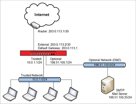
This scenario shows how to configure an optional network to use a public subnet IP address of 198.51.100.0/24, and how to configure policies for traffic to and from that subnet.
This single-WAN configuration has these characteristics:
- Single external interface
- Static routing
- Works with subnets of variable sizes
Configuration Summary:
- Add a static route on the router between the Firebox and the Internet.
- Assign a public IP address from the optional network public subnet to the Firebox optional interface.
- Make sure the public subnet is not included in the dynamic NAT configuration, because we do not want to do address translation for outbound traffic from this subnet.
Router Configuration
In this scenario, the router between the Firebox and the Internet has the IP address 203.0.113.1. Before you can use this Firebox configuration you must add a static route to the router that connects to the external interface. For this example, the router must have a static route to the public subnet 198.51.100.0/24 with the next hop to 203.0.113.2, the IP address of the Firebox external interface.
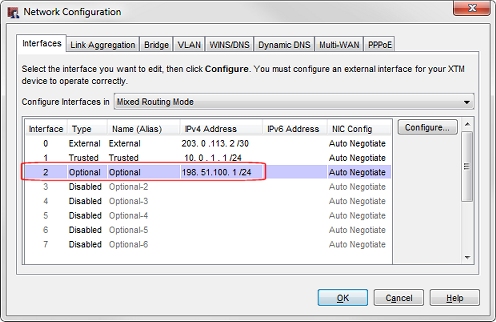
Firebox Network Configuration
The optional interface is configured with an IP address on the 198.51.100.0/24 public subnet.
Policy Configuration
You can create policies to handle inbound traffic to the public IP addresses of servers on your internal network. In the example configuration, the policy SMTP-proxy-in handles inbound traffic to a mail server on the optional network. In this case, 198.51.100.25 is the public IP address of a mail server on the optional network. The IP address of the mail server is the destination IP address in this policy.
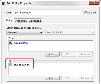
This example is for traffic to an SMTP server. You could also create policies that handle incoming traffic to other servers on this public subnet.
It is not necessary to create separate outgoing policies to handle outbound traffic from public servers on this network, because the default Outgoing policy already allows this traffic. We do not want to use NAT for outbound traffic from servers on this optional network. Even though the Outgoing policy has NAT enabled (in the Advanced tab), no NAT occurs for outgoing traffic from this optional network, because the public IP address range of this subnet is not specified in any of the dynamic NAT or 1-to-1 NAT entries.
Scenario 2 — Public Subnet on Optional, Single-WAN, Supernet
You might not want to allocate an entire /24 subnet to a network behind your Firebox. As an alternative, you can use a larger netmask to divide a subnet into smaller subnets, that you can use on different Firebox interfaces. The original subnet that you divide is a supernet of the smaller subnets.
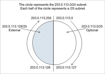
For example, if your ISP has allocated you the public IP address subnet 203.0.113.0/24, you can use the /25 netmask to split this subnet into two smaller subnets. You can then use one of the smaller subnets for your optional network, and the other smaller subnet for your external network. Here is an example of how that division works.
The subnet 203.0.113.0/24 includes IP addresses 203.0.113.0 - 203.0.113.255
You can use the /25 netmask, to split this /24 subnet into two /25 subnets which each contain half of the addresses in the original subnet.
The subnet 203.0.113.0/25 includes IP addresses 203.0.113.0 - 203.0.113.127
The subnet 203.0.113.128/25 includes IP addresses 203.0.113.128 - 203.0.113.255
The /24 network is a supernet of the two /25 subnets. You can visualize the supernet / subnet relationship for this example like this:
This example splits a /24 subnet into two smaller subnets. You can further reduce the /25 subnet assigned to the external interface if you want to assign more public IP addresses to other interfaces behind the Firebox.
Scenario 2 is similar to scenario 1, except that it shows how to use a public subnet of 203.0.113.0/25 for the optional network, and 203.0.113.128/25 for the external network.
This single-WAN configuration has these characteristics:
- Single external interface
- Static routing
- Uses the /25 netmask to break a /24 subnet into two smaller subnets
This configuration is the same as Scenario 1, except for the network addresses used on the external and optional networks.
Configuration Summary:
- Add a static route on the router between the Firebox and the Internet.
- Assign a public IP address from the /25 external network subnet to the external interface
- Assign a public IP address from the /25 optional network public subnet to the Firebox optional interface.
- Make sure the public subnet is not included in the dynamic NAT configuration, because we do not want to do address translation for outbound traffic from this subnet.
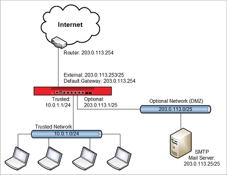
Router Configuration
In this scenario, the router between the Firebox and the Internet has the IP address 203.0.113.254. Before you can use this Firebox configuration you must add a static route to the router that connects to the external interface. For this example, the router must have a static route to the public subnet 203.0.113.0/25 with the next hop to 203.0.113.253, the IP address of the Firebox external interface.
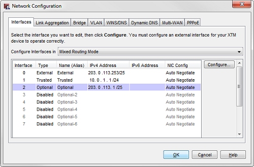
Firebox Network Configuration
The external interface is configured with the IP address 203.0.113.253/25 (an IP address from the 203.0.113.128/25 subnet).
The optional interface is configured with the IP address 203.0.113.1/25 (an IP address in the 203.0.113.0/25 subnet).
Policy Configuration
You can create policies to handle inbound traffic to the public IP addresses of servers on your internal network. In the example configuration, the policy SMTP-proxy-in handles inbound traffic to a mail server on the optional network. In this case, 203.0.113.25 is the public IP address of a mail server on the optional network. The IP address of the mail server is the destination IP address in this policy.
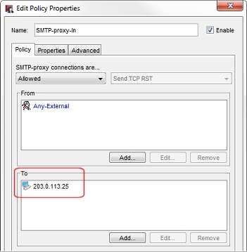
This example is for a mail server. You could also create policies that handle incoming traffic to other servers on this public subnet.
It is not necessary to create separate outgoing policies to handle outbound traffic from public servers on this network, because the default Outgoing policy already allows this traffic. We do not want to use NAT for outbound traffic from servers on this optional network. Even though the Outgoing policy has NAT enabled (in the Advanced tab), no NAT occurs for outgoing traffic from this optional network, because the public IP address range of this subnet is not specified in any of the dynamic NAT or 1-to-1 NAT entries.
Scenario 3 — Public Subnet on Optional, Multi-WAN
This multi-WAN configuration is similar to the single-WAN configuration, but supports failover between two external interfaces. This configuration would be appropriate if your Firebox connects to two different ISPs for Internet access.
This configuration has these characteristics:
- Two external interfaces, External-1 and External-2
- Static routing
- Works even with a subnet smaller than /24
- Inbound path to the real public IP address is still on a single path
Configuration Summary:
- Add a static route on the router between Firebox External-1 interface and the Internet.
- Assign a public IP address from the optional network public subnet to the Firebox optional interface.
- Add a dynamic NAT entry to translate the public subnet to the IP address of External-2, for outbound traffic through the External-2 interface.
- Configure inbound policies with two entries that go to the same host, one for traffic from each external interface.
- Disable 1-to-1 NAT in policies that involve the optional network or any host on the optional network that uses the public subnet.
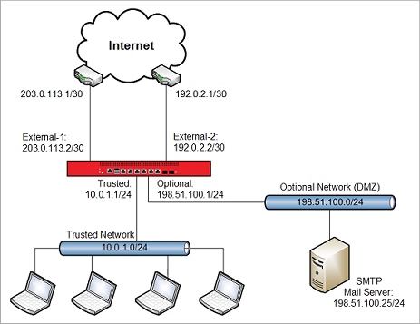
Router Configuration
Before you can use this Firebox configuration you must add a static route to the router that connects to the External-1 interface. For this scenario, the router must have a static route to the public subnet 198.51.100.0/24 with the next hop to 203.0.113.2, the IP address of the Firebox external interface.
You do not need to add a static route to the router that connects to the External-2 interface. Instead, you use a static NAT rule in the inbound policy to route traffic received by the External-2 interface to the public IP address of a host on the Optional network.
Firebox Network Configuration
Just as in the single-WAN configuration, the optional interface is configured with an IP address on the 198.51.100.0/24 public subnet.
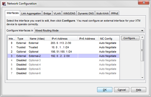
This configuration includes two external interfaces, External-1 (203.0.113.2/30), and External-2 (192.0.2.2/30).
Dynamic NAT Configuration
The configuration includes an added dynamic NAT rule for outbound traffic from the optional network to the External-2 interface.
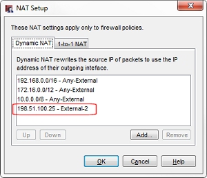
The dynamic NAT rule is 198.51.100.25 - External-2.
For outbound traffic from the SMTP server that leaves the External-2 interface, this dynamic NAT rule changes the source IP address from 198.51.100.25 to the IP address of the External-2 interface.
If you have other servers on the optional public IP subnet, you would add those entries to the dynamic NAT configuration as well. For example, if this network had a web server with IP address 198.51.100.80, the dynamic NAT rule would be 198.51.100.80 - External-2.
Policy Configuration
You can create policies to handle inbound traffic to the public IP addresses of servers on your internal network. In the example configuration, the policy SMTP-proxy-in handles inbound traffic to a mail server on the optional network. In this case, 198.51.100.25 is the public IP address of a mail server on the optional network. Because traffic to this mail server can arrive through one of two external interfaces, the destination address in this policy has two entries:
- The real public IP address of the mail server (198.51.100.25)
- A static NAT entry that translates the External-2 IP address (192.0.2.2) to the real IP address of the mail server (198.51.100.25)

Dynamic NAT and static NAT work together in this configuration to handle IP address translation for traffic that goes through the External-2 interface.
- Dynamic NAT — handles address translation for outbound traffic that leaves the External-2 interface.
- Static NAT — handles address translation for inbound traffic to the SMTP server that enters the External-2 interface.
DNS Records
With this multi-WAN configuration there are two public IP addresses that can be used to connect to each server. So you must configure DNS records to handle inbound traffic on either address. For each host, you need a DNS record with the real public IP address of the host (which is routable through the IP address on the External-1 interface), and a second DNS record with the IP address of the External-2 interface.
For this example network that has a mail server with the public IP address of 198.51.100.25, the NS records for the mail server could look like this:
company.com IN MX 5 mail1.company.com
company.com IN MX 10 mail2.company.com
mail1 IN A 198.51.100.25
mail2 IN A 192.0.2.2
If this example network had a web server with a public IP address of 198.51.100.80 on the optional network, the NS records for a web server could look like this:
www1.company.com. IN A 198.51.100.80
www2.company.com. IN A 192.0.2.2
This configuration example covers multi-WAN with static routing. You can also configure a public subnet (/24 or greater) behind the Firebox if you use dynamic routing.
Outgoing Policies
Our example configuration files do not include specific policies to handle outbound traffic from public servers on this network, because the default Outgoing policy already allows this traffic. If you remove the Outgoing policy from your configuration, or if you want the ability to more easily monitor the log messages related to traffic from these public servers, we recommend that you create a unique policy to handle outgoing traffic from each public server. For example, you could add a proxy policy that handles outgoing traffic from the mail server to any external interface. That policy could look like this:
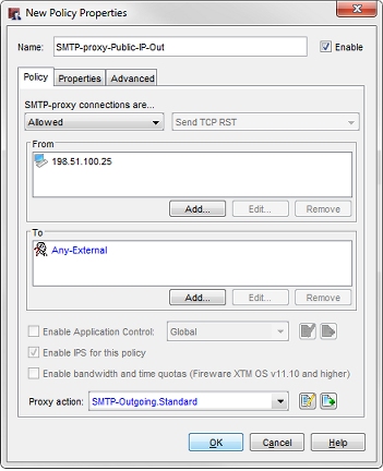
This policy handles outbound SMTP traffic from the server at 198.51.100.25 to any external interface. If you have other servers with public IP addresses on your network, you can create a policy to handle outbound traffic from each server.
Conclusion
In this configuration example, we have shown three ways that you can configure a subnet with public IP addresses on an optional network protected by your Firebox. The three configuration scenarios should give you some ideas about how you can use NAT to route traffic to publicly routable IP addresses on the network protected by your Firebox.
If you would rather use private IP addresses for publicly accessible servers on your private network, that is also an option.