The objective of this configuration example is to show how an organization with networks at two sites can use a branch office VPN to connect the two networks. To increase the total throughput between sites and to make their VPN connection more fault-tolerant, in this example we set up a second VPN tunnel between the two sites, and load balance connections through both VPN tunnels.
This configuration example is provided as a guide. Additional configuration settings might be necessary, or more appropriate, for your network environment.
Solution Overview
A BOVPN virtual interface provides a secure VPN tunnel for traffic between the networks protected by two Fireboxes. You can configure a second BOVPN virtual interface to send traffic through a second external interface. This configuration example shows how to set up two BOVPN virtual interfaces between two sites and use OSPF to load balance connections through the two VPN tunnels with equal priority.
Requirements
For the BOVPN virtual load balancing described in this example to operate correctly, each Firebox must use Fireware v11.9 or higher, and each Firebox must have two external interfaces.
OSPF supports ECMP (equal cost multipath) load balancing. If multiple routes to the same destination have an equal route metric, OSPF uses ECMP to evenly distribute traffic across multiple routes based on source and destination IP addresses, and the number of connections that currently use each route. In this example configuration, two BOVPN virtual interfaces are configured between two Fireboxes. Each VPN uses a different external interface. The two devices use OSPF to exchange information about routes to their local networks through both tunnels. Because the point-to-point connections through each tunnel have the same metric, OSPF load balances traffic through both tunnels with equal priority.
With this configuration:
- Each Firebox uses OSPF to propagate routes to local networks through both BOVPN virtual interfaces.
- When both VPN tunnels are available, OSPF uses ECMP to load balance connections through the two VPN tunnels.
- If one external interface or one tunnel goes down, OSPF automatically sends all traffic through the other BOVPN tunnel.
Configuration
In this configuration example, we present an organization that has Fireboxes at two locations: one in Hamburg, and another in Berlin. This example shows how to set up two VPN tunnels and load balance traffic through both tunnels with equal priority.
Topology
This configuration example includes the IP addresses in this diagram.

Network Configuration
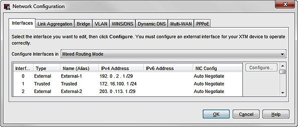
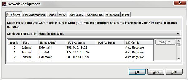
We used these IP addresses for each site:
| Firebox Interface | Berlin | Hamburg |
|---|---|---|
| External-1 | IP address: 192.0.2.1/29 Default GW: 192.0.2.6 |
IP address: 192.0.2.9/29, Default GW: 192.0.2.14 |
| External-2 | IP address: 203.0.113.1/29 Default GW: 203.0.113.6 |
IP address: 203.0.113.9/29 |
| Trusted network |
172.16.100.0/24 |
172.16.101.0/24 |
How It Works
Multi-WAN Configuration
In this example, we created a configuration file for the Berlin Firebox. The Berlin Firebox has two external interfaces, External-1 and External-2, and one trusted interface
We also create a configuration file for the Hamburg Firebox. The Hamburg Firebox has two external interfaces, External-1 and External-2, and one trusted interface.
Both Fireboxes are configured to use the Routing Table multi-WAN method. The multi-WAN method controls load balancing for non-IPSec traffic routed through the external interfaces. The multi-WAN settings do not enable load balancing of IPSec traffic through the tunnel. The load balancing of traffic through the tunnel is a function of OSPF, as configured in the next section.
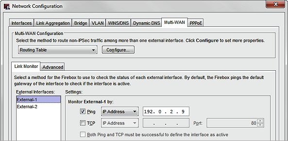
In this example multi-WAN configuration, each Firebox uses the external IP address of the peer device as a ping link monitor target for each external interface. The ping target is not required, but we recommend that you configure a reliable link monitor target any time you configure multi-WAN.
BOVPN Virtual Interfaces
BOVPN virtual interfaces for VPN connections between each site. Each Firebox has two BOVPN virtual interfaces.
To create the BOVPN virtual interfaces, select VPN > BOVPN Virtual Interfaces.
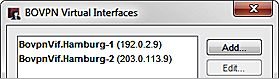
The Berlin Firebox has two BOVPN virtual interfaces:
- BovpnVif.Hamburg-1 — Uses the External-1 interface
- BovpnVif.Hamburg-2 — Uses the External-2 interface
The Hamburg Firebox has two BOVPN virtual interfaces:
- BovpnVif.Berlin-1 — Uses the External-1 interface
- BovpnVif.Berlin-2 — Uses the External-2 interface
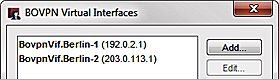
Each device has two BOVPN virtual interfaces. Each BOVPN virtual interface is named to represent the location of the remote device, and which local external interface it uses.
For each BOVPN virtual interface, the remote gateway ID is an external IP address on the peer Firebox.
VPN-1 Configuration on the Berlin Firebox
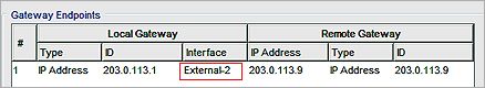
On the Berlin Firebox, we configured the external interface External-1 to connect to the remote gateway at the Hamburg Firebox.
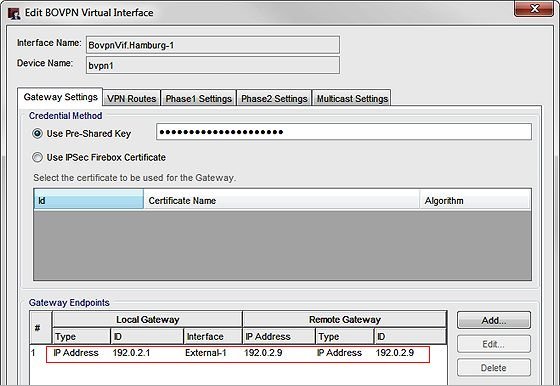
In the Gateway Settings tab, we set:
- The Local Gateway ID to the IP address of the local External-1 interface, 192.0.2.1
- The Interface to External-1.
- The Remote Gateway IP Address and ID to the IP address of the external interface on the Hamburg Firebox, 192.0.2.9.
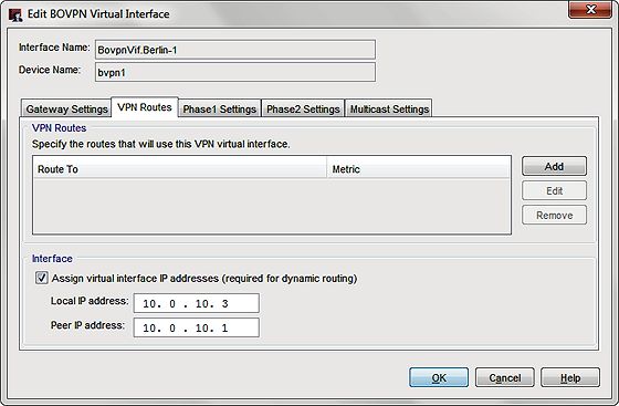
To configure dynamic routing through a BOVPN virtual interface, you must assign virtual interface IP addresses in the VPN Routes tab.
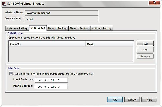
In the VPN Routes tab, the virtual IP addresses are set to:
- Local IP address: 10.0.10.1
- Peer IP address: 10.0.10.3
For this example, the virtual interface IP addresses used for both tunnels are all in the 10.0.10.0/24 subnet. This subnet is used in the OSPF configuration to define a point-to-point network.
VPN-1 Configuration on the Hamburg Firebox
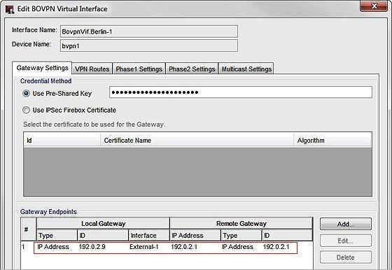
On the Hamburg Firebox, BovpnVif.Berlin-1 uses the external interface External-1 to connect to the remote gateway at the BerlinFirebox.
In the Gateway Settings tab, we set:
- The Local Gateway ID to the IP address of the local External-1 interface, 192.0.2.9 and the Interface to External-1.
- The Remote Gateway IP Address and ID to the IP address of the external interface on the Berlin Firebox, 192.0.2.1.
A Local IP address and Peer IP address are configured in the VPN Routes tab. These IP addresses are used in the OSPF configuration to define a point-to-point network. These IP addresses must be the opposite of the addresses configured for this tunnel on the peer Firebox.
In the VPN Routes tab, we set the virtual IP addresses to:
- Local IP address: 10.0.10.3
- Peer IP address: 10.0.10.1
VPN-2 Configuration on the Berlin Firebox
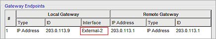
The second BOVPN virtual interface on each device is configured very similarly, except that the gateway endpoints specify the second external interface, External-2, and use the IP addresses of the second external interface on each device as the local and remote gateway endpoints.
In the Gateway Settings tab, we set:
- The Local Gateway ID to the IP address of the local External-2 interface, 203.0.113.1
- The Interface to External-2.
- The Remote Gateway IP Address and ID to the IP address of the external-2 interface on the Hamburg Firebox, 203.0.113.9.
In the VPN Routes tab, we set the virtual IP addresses to:
- Local IP address: 10.0.10.4
- Peer IP address: 10.0.10.2
VPN-2 Configuration on the Hamburg Firebox
In the Gateway Settings tab, we set:
- The Local Gateway ID to the IP address of the local External-2 interface, 203.0.113.9
- The Interface to External-2.
- The Remote Gateway IP Address and ID to the IP address of the external-2 interface on the Hamburg Firebox, 203.0.113.2.
In the VPN Routes tab, we set the virtual IP addresses to:
- Local IP address: 10.0.10.2
- Peer IP address: 10.0.10.4
These IP addresses are the opposite of the addresses configured for this tunnel on the peer Firebox.
Dynamic Routing Configuration
In the example dynamic routing configuration:
- The router-id is set to the IP address of the trusted interface.
- All interfaces are passive except the two BOVPN virtual interfaces, bvpn1 and bvpn2.
- Each Firebox announces 10.0.10.0/24, the subnet used for the point-to-point networks through each tunnel.
- The local and peer IP addresses for both BOPVN virtual interfaces fall within this subnet.
- Each Firebox announces its own trusted network:
- The Berlin Firebox announces 172.16.100.0/24
- The Hamburg Firebox announces 172.16.101.0/24
Dynamic routing configuration on the Berlin Firebox:
router ospf
ospf router-id 172.16.100.1
! exclude all but bvpn virtual interfaces
passive-interface default
no passive-interface bvpn1
no passive-interface bvpn2
! which networks are announced in OSPF area 0.0.0.0
! bvpn Point-to-Point networks
network 10.0.10.0/24 area 0.0.0.0
! Trusted network
network 172.16.100.0/24 area 0.0.0.0
Dynamic routing configuration on the Hamburg Firebox:
router ospf
ospf router-id 172.16.101.1
! exclude all but bvpn interfaces
passive-interface default
no passive-interface bvpn1
no passive-interface bvpn2
! which networks are announced in OSPF area 0.0.0.0
! bvpn Point-to-Point networks
network 10.0.10.0/24 area 0.0.0.0
! Trusted network
network 172.16.101.0/24 area 0.0.0.0
Dynamic Routes
After the configuration is saved to the two Fireboxes, the routes propagate through the tunnel to each device. With this configuration, each device has two routes to the remote trusted network. Both routes have the same metric, and each uses a different virtual interface. After the tunnels are established between the two devices, you can see the learned routes in the Status Report.
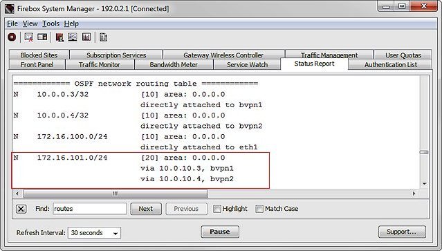
Routes on the Berlin Firebox
The IPv4 Routes section of the Status Report on the Berlin Firebox shows the two routes to the trusted network on the Hamburg trusted network, one through bvpn1 and one through bvpn2.
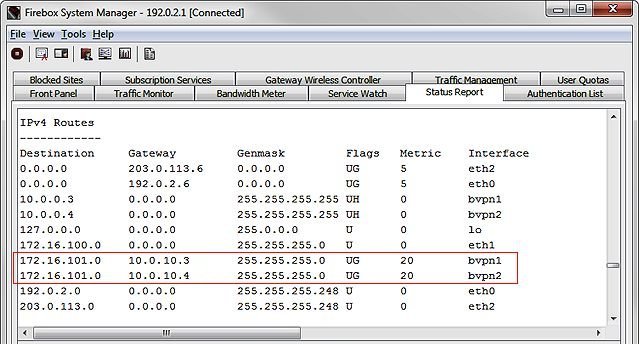
The OSPF network routing table shows the two routes through each BOVPN virtual interface.
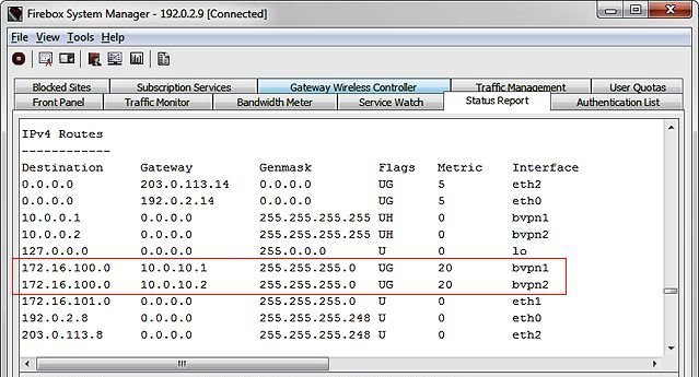
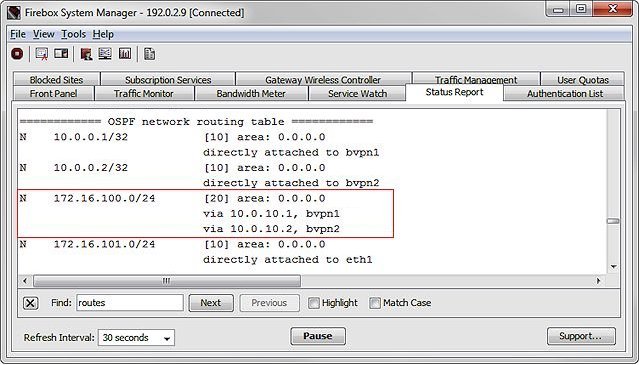
Routes on the Hamburg Firebox
On the Hamburg Firebox, the IPv4 Routes table shows two routes to the trusted network of the Berlin Firebox.
The OSPF network routing table shows the two routes through each BOVPN virtual interface.
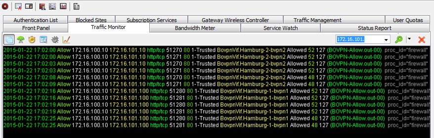
Monitor VPN Load Balancing
In Firebox System Manager you can monitor the load balancing through the two VPN tunnels. The images below show an example of what the load balancing looks like when monitored from the Berlin Firebox.
On the Traffic Monitor tab, you can see that both VPN tunnels are used for connections from different clients.
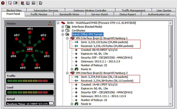
On the Front Panel tab you can monitor the traffic statistics for both VPN interfaces to see the traffic load balanced through both tunnels.
Conclusion
This configuration example demonstrates how to configure OSPF to do load balancing through two BOVPN virtual interfaces. This type of configuration provides redundancy for the secure connection between the two networks, as well as load balancing of IPSec VPN traffic through two external interfaces. You could extend this configuration to load balance connections through more than two VPN tunnels if both devices have additional external interfaces.
Configure a BOVPN Virtual Interface
BOVPN Virtual Interface with Dynamic Routing