The objective of this configuration example is to show how an organization with multiple sites of different sizes can interconnect the networks at each site. In this example, an organization wants visibility and control of their data at a central location. They could also want a central reliable location for their resources, or could have business processes that require a centralized architecture.
This configuration example is provided as a guide. Additional configuration settings might be necessary, or more appropriate, for your network environment.
Solution Overview
In a centralized VPN configuration, also referred to as hub and spoke, all VPN tunnels converge at one location. This can be used to achieve global data visibility and control at a central location. This solution can help maintain resource availability because all shared resources can be placed in a well maintained, reliable location.
This configuration example relies heavily upon the central location, because the central location is a possible single point of failure for VPN tunnels. If the organization adds more remote locations, it could be necessary to expand the capacity of the central location. If network resources are primarily dispersed among the remote sites, a decentralized architecture could be a better solution.
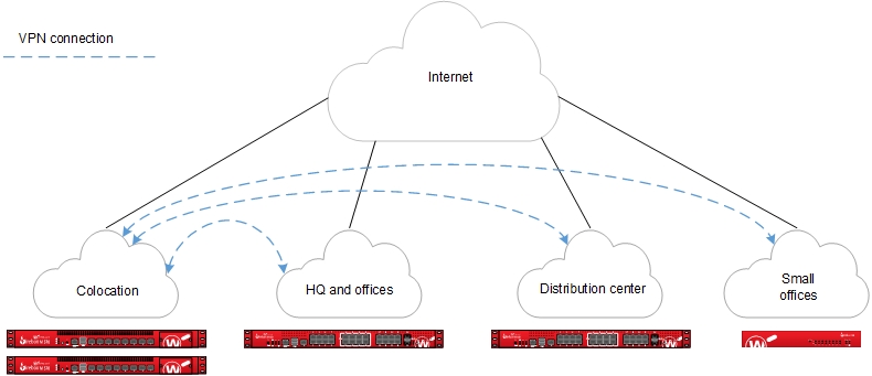
The Firebox at the central location acts as the primary gateway for VPN tunnels from remote network sites. The central location receives all data transferred between sites. If the central location receives traffic that is not intended for a resource at the central location, the device at the central location redirects the traffic to the tunnel for the correct destination. This is known as tunnel switching.
Requirements
A reliable central location
The central location processes the aggregate of all VPN connections. All VPN traffic depends on the availability of this site.
Sufficient bandwidth
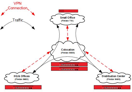
Switched tunnels require bandwidth at the source, destination, and the central location. As shown in the previous diagram, the Small Office that receives traffic from HQ uses the upstream bandwidth at HQ, the upstream and downstream bandwidth at Colocation, and the downstream bandwidth at Small Office. Due to encryption and encapsulation overhead, VPN bandwidth is measured at less than line speed.
A Firebox appropriate for each location
Firebox capabilities vary by model. For VPN configurations, you must consider the VPN throughput and tunnel capacity of each model. Network environment, configuration options, and other factors can also help you determine the most appropriate model for each site.
VPN throughput is the amount of data passed over the VPN per second. The central location processes switched traffic twice.
VPN tunnel count is determined by the number of connected networks (as configured in tunnel routes). For offices, this is generally the number of local networks multiplied by the number of remote networks. For the central location, this is the sum total of the tunnel count at all other locations.
For more information about the VPN throughput and branch office VPN tunnel capacity available for each Firebox model, refer to the product datasheets: https://www.watchguard.com/wgrd-resource-center/product-resources.
Configuration
In this example, we present an organization that has four locations: a colocation facility (Colo), a corporate office (Corp), a distribution center (Dist), and a small office (RMT). You can also scale up this solution to support additional offices, distribution centers, and small offices.
Topology
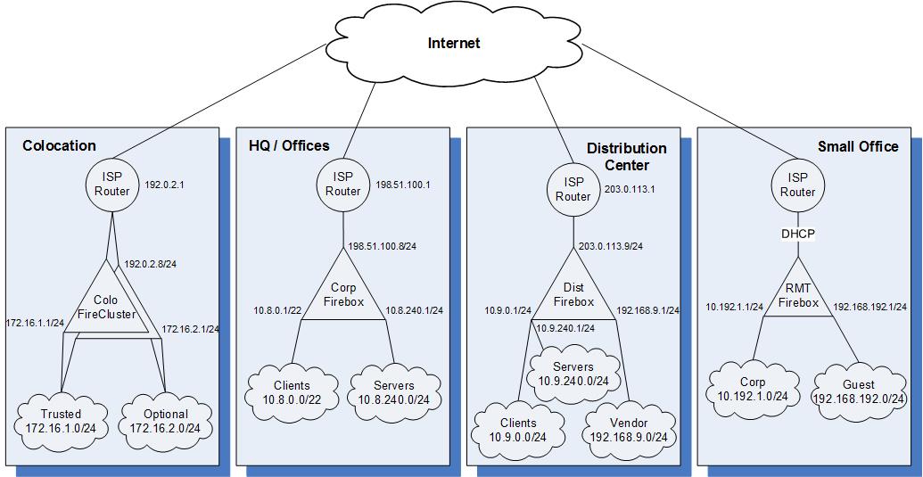
The sample IP addresses for the sites in this configuration:
| Colo | Corp | Dist | RMT | |
|---|---|---|---|---|
| External interface IP address | 192.0.2.8/24 | 198.51.100.8/24 | 203.0.113.9/24 | DHCP |
| Default gateway IP address | 192.0.2.1 | 198.51.100.1 | 203.0.113.1 | DHCP |
| Private network allocated to site | 172.16.0.0/16 | 10.8.0.0/16 | 10.9.0.0/16 | 10.192.1.0/24 |
| Un-routed network allocated to site | N/A | N/A | 192.168.9.0/24 | 192.168.192.0/24 |
How It Works
Branch Office VPN Gateways
Create configuration files that contain branch office gateways defined for VPN connections between the Colocation Firebox and Fireboxes at the other sites.
To see the branch office VPN gateways:
- Open the Firebox configuration in Policy Manager.
- Select VPN > Branch Office Gateways.
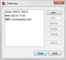
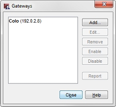
In this image, our Colo configuration has three gateways, one for each other site. At each of the other sites, the configuration has only one gateway to the Colo site.
Branch Office VPN Tunnels
Create configuration files that contain branch office tunnels defined to route traffic between the networks at each site.
To see the branch office VPN tunnels:
- Open the Firebox configuration in Policy Manager.
- Select VPN > Branch Office Tunnels.
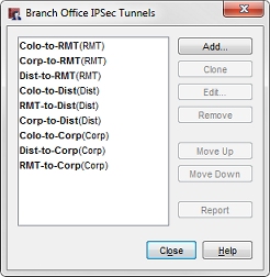
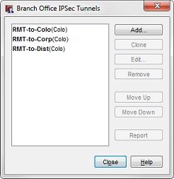
In this image, you can see our colocation (Colo) configuration has nine tunnels, while the small office (RMT) has three.
The small office must have tunnels defined only for routes from its local networks to remote networks, but the colocation site must have tunnels defined for all interconnected networks. In our configuration files, each tunnel is named to represent the local and remote networks it manages. The identifier in parentheses is the gateway used by the tunnel.
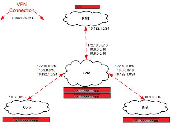
The tunnel routes have been defined with the subnets allocated to each site, instead of the individual networks defined for the site. In this configuration, the small office (RMT) only requires three tunnel routes, as opposed to six tunnel routes to reach the trusted and optional networks at each of the other sites. Any new networks in this allocation that are established at each site are routed over the existing branch office VPN. For more granular control of VPN tunnels, you can define each individual network at a cost of additional tunnel routes and administration time.

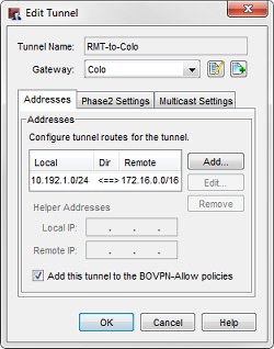
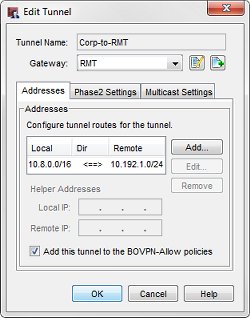
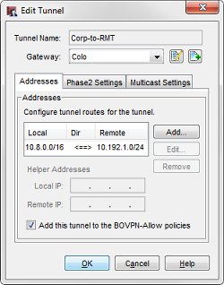
For example, the tunnel routes Colo-to-RMT and RMT-to-Colo use the subnet IP address 172.16.0.0/16 as the address of the Colo network. This enables these tunnels to handle all traffic between the small office (RMT) network and the Colo trusted (172.16.1.0) and optional (172.16.2.0) networks.
When you look at the tunnel routes, remember that the local-remote pairs are defined relative to the two endpoint networks for the tunnel traffic. In some cases, the local address in a VPN tunnel route is the address of a network at another connected site. For example, in the Colo configuration, the Corp-to-RMT tunnel route uses the network IP address of the trusted network at Corp as local, even though it is not physically located at the Colo site.
This diagram shows all of the local and remote IP addresses of the tunnel routes configured between each location.
Tunnel Switching in Action
Now we can use the example configuration to follow the path a packet takes when a user at one location establishes a connection to a resource at a different location over switched tunnels.
A user at the small office (10.192.0.100) tries to connect to a resource at the corporate office (10.8.240.80). The packet first reaches the RMT Firebox. The RMT Firebox determines that the destination of the packet is available through the RMT-to-Corp tunnel to the Colo gateway.

The RMT Firebox sends this packet through the RMT-to-Corp (Colo) tunnel.
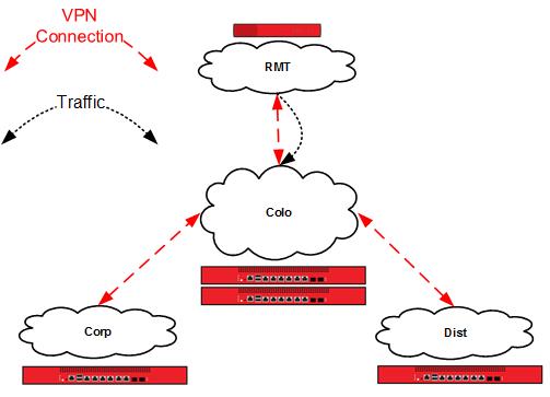
The Colo Firebox receives this traffic identified as part of the Corp-to-RMT (RMT) tunnel in its local configuration. The local network IP address in this tunnel route is local to the Corp site, not the Colo site.
The RMT Firebox determines that the destination of the decrypted packet is available through the RMT-to-Corp (Corp) tunnel to the Corp gateway.
The Colo Firebox switches the traffic from the Corp-to-RMT (RMT) tunnel to the RMT-to-Corp (Corp) tunnel.
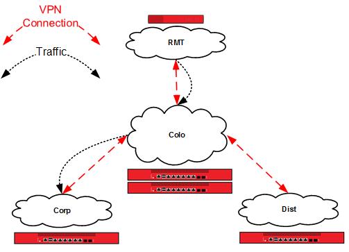
The Corp Firebox receives this traffic identified as part of the Corp-to-RMT (Colo) tunnel, and delivers the decrypted packet to its destination, a server on the corporate office local network.
Conclusion
This configuration example demonstrates how to configure tunnel switching in a hub and spoke network topology to route VPN traffic between sites that are not directly connected to each other. This type of configuration is most appropriate for an organization that has multiple sites, and that has most of the shared network resources at a central location. The configuration described here can scale up to support additional remote sites.
This example also shows how to use subnet IP addresses in the tunnel route configuration to reduce the number of tunnels you must configure to connect private networks at each site.