Use a Branch Office VPN for Failover from a Leased Line (OSPF)
This topic provides an example of how to configure failover from a leased line that uses OSPF to a branch office VPN. For an overview of how failover to a branch office VPN works, go to Configure a Branch Office VPN for Failover from a Leased Line.
In this example, an organization has a leased line that connects Fireboxes at two sites, Site 1 and Site 2. The router for the leased line is connected to the trusted network at each site. The network administrator for the organization wants to configure a branch office VPN connection between the two sites, which can be used for failover if the leased line connection becomes unavailable.
This diagram shows the configuration settings that apply to each site for this example.
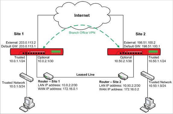
Site 1 Network Configuration
WatchGuard Firebox at Site 1:
- External interface IP address: 203.0.113.2/24
- Default gateway IP address: 203.0.113.1
- Trusted-1 interface IP address: 10.0.1.1/24 — connected to the Site 1 trusted network
- Trusted network IP address: 10.0.1.0/24
- Trusted-2 interface IP address: 10.0.2.1/30 — connected to the router
Router connected to the leased line, and connected to the Site 1 optional interface:
- LAN IP address: 10.0.2.2/30
- WAN IP address: 172.16.0.1
Site 2 Network Configuration
WatchGuard Firebox at Site 2:
- External interface IP address: 198.51.100.2/24
- Default gateway IP address: 198.51.100.2.1
- Trusted-1 interface IP address: 10.50.1.1/24 — connected to the Site 2 trusted network
- Trusted network IP address: 10.50.1.0/24
- Trusted-2 interface IP address: 10.50.2.1/30 — connected to the router
Router connected to the leased line, and connected to the Site 2 trusted network:
- LAN IP address: 10.50.2.2/30
- WAN IP address: 172.16.0.2
Static Routes
There are routers at each end of the leased line between the two Fireboxes. At each site you must to configure static routes on the Firebox and on the router so the traffic can be routed correctly between the two networks.
The static routes needed on the Firebox and on the router at each site are shown below.
Static Routes at Site 1
| On Site 1 Firebox | On Site 1 Router | |
|---|---|---|
| Route to Site 2 Firebox |
Route to: 10.50.2.0/30 |
Network: 10.50.2.0/30 |
| Route to Site 1 trusted network |
|
Network: 10.0.1.0/24 |
| Route to Site 2 trusted network |
Network: 10.50.1.0/24 |
Static Routes at Site B
| On Site 2 Firebox | On Site 2 Router | |
|---|---|---|
| Route to Site 1 Firebox |
Route to: 10.0.2.0/30 |
Network: 10.0.2.0/30 |
| Route to Site 1 trusted network |
Network: 10.0.1.0/24 |
|
| Route to Site 2 trusted network |
Network: 10.50.1.0/24 |
For information about how to add a static route to the Firebox, go to Add a Static Route.
After you configure the static routes and verify that the devices can reach each other, you can configure dynamic routing across the private network link.
Configure Dynamic Routing at Site 1
To use the branch office VPN connection for failover, you must enable dynamic routing on the Firebox at each site. You can use any supported dynamic routing protocol (RIP v1, RIP v2, OSPF, or BGP v4). This example uses OSPF.
- Select Network > Dynamic Routing.
The Dynamic Routing Setup page appears - Select the Enable Dynamic Routing check box.
- Select the OSPF tab.
- Select the Enable check box.
- In the OSPF tab text box, paste the text of your routing daemon configuration file.
For Site 1, the OSPF routing daemon configuration file contains this text:
router ospf
ospf router-id 10.0.2.1
network 10.0.2.0/24 area 0
network 10.0.1.0/24 area 0
- Click Save.
When you enable dynamic routing, a policy is automatically added to allow traffic to the reserved multicast addresses used by OSPF. - Set up the router connected to the leased line at Site 1 to enable OSPF for dynamic routing.
For example, if Site 1 uses a Cisco router, add these lines to the router configuration file:
router ospf 1
log-adjacency-changes
network 172.16.0.0 0.0.0.255 area 0
network 10.0.2.0 0.0.0.255 area 0
- After you configure the router, select System Status > Routes and verify the Firebox and the router are connected and able to send updates to each other.
- Select Network > Dynamic Routing.
The Dynamic Routing Setup dialog box appears. - Select the Enable Dynamic Routing check box.
- Select the OSPF tab.
- Select the Enable OSPF check box.
- In the OSPF tab text box, paste the text of your routing daemon configuration file, or click Import to import a configuration file.
For Site 1, the OSPF routing daemon configuration file contains this text:
router ospf
ospf router-id 10.0.2.1
network 10.0.2.0/24 area 0
network 10.0.1.0/24 area 0
- Click Save.
When you enable dynamic routing, a policy is automatically added to allow traffic to the reserved multicast addresses used by OSPF. - Set up the router connected to the leased line at Site 1 to enable OSPF for dynamic routing.
For example, if Site 1 uses a Cisco router, add these lines to the router configuration file:
router ospf 1
log-adjacency-changes
network 172.16.0.0 0.0.0.255 area 0
network 10.0.2.0 0.0.0.255 area 0
- After you configure the router, open the Traffic and Performance Statistics (Status Report).
- In the dynamic routing section, verify that the Firebox and the router are connected and able to send updates to each other.
After you configure dynamic routing, you can configure authentication and restrict the OSPF policy to listen only on the correct interfaces.
Configure Dynamic Routing at Site 2
To configure dynamic routing at Site 2, repeat the same steps, with the appropriate addresses in the dynamic routing configuration.
- Select Network > Dynamic Routing to enable dynamic routing with OSPF on the Firebox at Site 2.
For Site 2, the OSPF routing daemon configuration file contains this text:
router ospf
ospf router-id 10.50.2.1
network 10.50.2.0/24 area 0
network 10.50.1.0/24 area 0
- Set up the router connected to the leased line at Site 2 to enable OSPF for dynamic routing.
For example, if you use a Cisco router, add these lines to the router configuration file:
router ospf 1
log-adjacency-changes
network 172.16.0.0 0.0.0.255 area 0
network 10.50.2.0 0.0.0.255 area 0
- After you configure the router, select System Status > Routes and verify the Firebox and the router are connected and able to send updates to each other.
- Select Network > Dynamic Routing to enable dynamic routing with OSPF on the Firebox at Site 2.
For Site 2, the OSPF routing daemon configuration file contains this text:
router ospf
ospf router-id 10.50.2.1
network 10.50.2.0/24 area 0
network 10.50.1.0/24 area 0
- Set up the router connected to the leased line at Site 2 to enable OSPF for dynamic routing.
For example, if you use a Cisco router, add these lines to the router configuration file:
router ospf 1
log-adjacency-changes
network 172.16.0.0 0.0.0.255 area 0
network 10.50.2.0 0.0.0.255 area 0
- After you configure the router, open the Traffic and Performance Statistics (Status Report).
- In the dynamic routing section, verify that the Firebox and the router are connected and able to send updates to each other.
Configure the Branch Office VPN at Site 1
This example uses the default Phase 1 and Phase 2 settings.
At Site 1, configure the branch office VPN gateway to Site 2
- Select VPN > Branch Office VPN.
- Adjacent to the Gateways list, click Add.
The Gateway settings page appears. - In the Gateway Name text box, type a name to identify the gateway.
For this example, type gateway to site 2. - Select Use Pre-Shared Key. Type a shared key to use on both devices.
- In the Gateway Endpoints section, click Add.
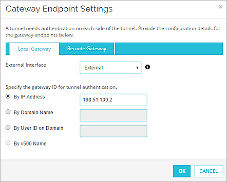
The Gateway Endpoint Settings dialog box appears.

- In the Local Gateway tab, in the By IP Address text box, type the external interface IP address for the Firebox at Site 1, 203.0.113.2.
- Select the Remote Gateway tab.
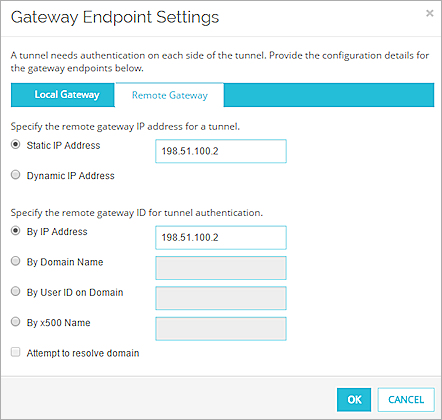
- In the Remote Gateway
- In the Remote Gateway section, for the gateway ID, type the External interface IP address for the Firebox at Site 2, 198.51.100.2.
- Click OK.
The Gateway Endpoints you added appear in the New Gateway dialog box. - Click Save.
- Select VPN > Branch Office Gateways.
- Click Add.
The New Gateway dialog box appears. - In the Gateway Name text box, type a name to identify the gateway.
For this example, type gateway to site 2. - Select Use Pre-Shared Key. Type a shared key to use on both devices.
- In the Gateway Endpoints section, click Add.
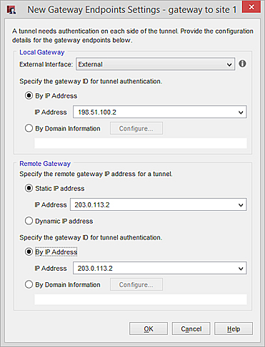
The New Gateway Endpoints dialog box appears
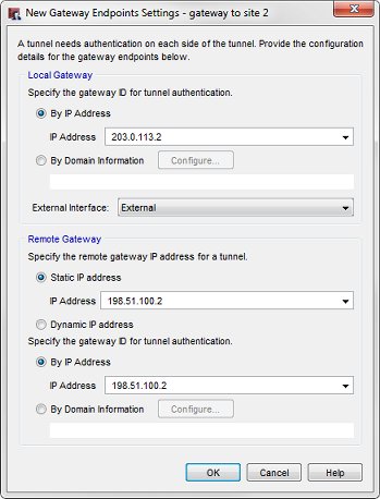
- In the Local Gateway section, in the IP Address text box, type the external interface IP address for the Firebox at Site 1, 203.0.113.2.
- Select the Remote Gateway tab.
- In the Remote Gateway section, for the remote gateway IP address, type the External interface IP address for the Firebox at Site 2, 198.51.100.2.
- In the Remote Gateway section, for the gateway ID, type the External interface IP address for the Firebox at Site 2, 198.51.100.2.
- Click OK.
The Gateway Endpoints you added appear in the New Gateway dialog box. - Click OK.
At Site 1, configure the branch office VPN tunnel to Site 2
- Select VPN > Branch Office Tunnels.
- Click Add.
The New Tunnel dialog box appears. - In the Tunnel Name text box, type a name for the tunnel.
- Click Add.
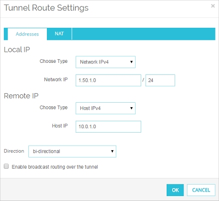
The Tunnel Route Settings dialog box appears.
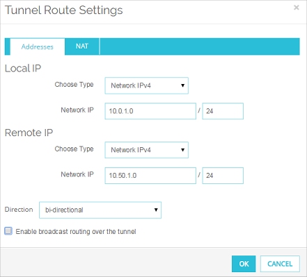
- In the Local IP section, from the Choose Type drop-down list, select Network IP.
- In the Network IP text box, type the IP address of the trusted network at Site 1, 10.0.1.0/24.
- In the Remote IP section, from the Choose Type drop-down list, select Network IP.
- In the Network IP text box, type the IP address of the trusted network at Site 2, 10.50.1.0/24.
- Click OK.
The tunnel route appears in the New Tunnel dialog box.
- Select VPN > Branch Office Tunnels.
- Click Add.
The New Tunnel dialog box appears. - In the Tunnel Name text box, type a name for the tunnel.
- Click Add.
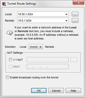
The Tunnel Route Settings dialog box appears.

- In the Local text box, type the IP address of the trusted network at Site 1, 10.0.1.0/24.
- In the Remote text box, type the IP address of the trusted network at Site 2, 10.50.1.0/24.
- Click OK.
The tunnel route appears in the New Tunnel dialog box.
At Site 1, in the Global VPN Settings, enable failover to the VPN.
- Select VPN > Global Settings.
The Global VPN Settings dialog box appears.
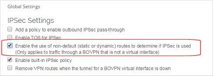
- Select the Enable the use of non-default (static or dynamic) routes to determine if IPSec is used check box.
- Click Save.
- Select VPN > VPN Settings.
The VPN Settings dialog box appears.
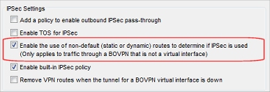
- Select the Enable the use of non-default (static or dynamic) routes to determine if IPSec is used check box.
- Click OK.
- Save the configuration to the device.
Configure the Branch Office VPN at Site 2
At Site 2, configure the branch office VPN gateway to Site 1
- Select VPN > Branch Office Gateways.
- Click Add.
The New Gateway dialog box appears. - In the Gateway Name text box, type a name to identify the gateway.
For this example, type gateway site 1. - Select Use Pre-Shared Key. Type a shared key to use on both devices.
- In the Gateway Endpoints section, click Add.
The New Gateway Endpoints dialog box appears.
- In the Local Gateway tab, type the External interface IP address for the Firebox at Site 2, 198.51.100.2.
- Select the Remote Gateway tab.

- In the Remote Gateway, for the remote gateway IP address, type the External interface IP address for the Firebox at Site 1, 203.0.113.2.
- For the gateway ID, type the External interface IP address for the Firebox at Site 1, 203.0.113.2.
- Click OK.
The Gateway Endpoints you added appear in the New Gateway dialog box. - Click Save.
- Select VPN > Branch Office Gateways.
- Click Add.
The New Gateway dialog box appears. - In the Gateway Name text box, type a name to identify the gateway.
For this example, type gateway site 1. - Select Use Pre-Shared Key. Type a shared key to use on both devices.
- In the Gateway Endpoints section, click Add.
The New Gateway Endpoints dialog box appears.
- In the Local Gateway section, type the External interface IP address for the Firebox at Site 2, 198.51.100.2.
- Select the Remote Gateway tab.
- In the Remote Gateway section, for the remote gateway IP address, type the External interface IP address for the Firebox at Site 1, 203.0.113.2.
- For the gateway ID, type the External interface IP address for the Firebox at Site 1, 203.0.113.2.
- Click OK.
The Gateway Endpoints you added appear in the New Gateway dialog box. - Click OK.
At Site 2, configure the branch office VPN tunnel to Site 1
- Select VPN > Branch Office Tunnels.
- Click Add.
The New Tunnel dialog box appears. - In the Tunnel Name text box, type a name for the tunnel.
- Click Add.
The Tunnel Route Settings dialog box appears.
- In the Local IP section, from the Choose Type drop-down list, select Network IP.
- In the Network IP text box, type the IP address of the trusted network at Site 2, 10.50.1.0/24.
- In the Remote IP section, from the Choose Type drop-down list, select Network IP.
- In the Network IP text box, type the IP address of the trusted network at Site 1, 10.0.1.0/24.
- Click OK.
The tunnel route appears in the New Tunnel dialog box.
- Select VPN > Branch Office Tunnels.
- Click Add.
The New Tunnel dialog box appears. - In the Tunnel Name text box, type a name for the tunnel.
- Click Add.
The Tunnel Route Settings dialog box appears.
- In the Local text box, type the IP address of the trusted network at Site 2, 10.50.1.0/24.
- In the Remote text box, type the IP address of the trusted network at Site 1, 10.0.1.0/24.
- Click OK.
The tunnel route appears in the New Tunnel dialog box.
At Site 2, in the Global VPN Settings, enable failover to the VPN.
- Select VPN > Global Settings.
The Global VPN Settings dialog box appears.
- Select the Enable the use of non-default (static or dynamic) routes to determine if IPSec is used check box.
- Click Save.
- Select VPN > VPN Settings.
The VPN Settings dialog box appears.
- Select the Enable the use of non-default (static or dynamic) routes to determine if IPSec is used check box.
- Click OK.
- Save the configuration to the device.
Configure a Branch Office VPN for Failover from a Leased Line
Use a Branch Office VPN for Failover from a Leased Line (BGP)