Configure Manual Branch Office VPN Tunnel Switching
When you connect two or more remote BOVPN tunnels to your network, you must configure tunnel switching if you want the computers on each remote network to exchange data. When you set up this feature, the Firebox decrypts packets sent from one VPN and sends the re-encrypted packets to their destination on the other VPN.
This topic provides an example of how to configure BOVPN tunnel switching. For detailed information about the BOVPN configuration settings used in this example, go to About Manual IPSec Branch Office VPNs.
Overview
In this example, we demonstrate how to pass traffic from the trusted network of Remote Office A to the trusted network of Remote Office B without creating a third BOVPN tunnel between the two remote offices. This scenario is useful when you require control of network security at the Central Office, because you can apply policies to traffic between Sites A and B at the Central Office.
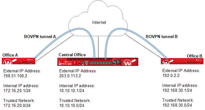
This diagram shows the topology.
IP Address Configuration
Remote Office A Firebox Addresses
External interface IP address: 198.51.100.2/24
Default Gateway: 198.51.100.1
Trusted interface IP address: 172.16.20.1/24
Private network IP address: 172.16.20.0/24
Central Office Firebox Addresses
External interface IP address: 203.0.113.2/24
Default Gateway: 203.0.113.1
Trusted interface IP address: 10.10.10.1/24
Private network IP address: 10.10.10.0/24
Remote Office B Firebox Addresses
External interface IP address: 192.0.2.2/24
Default Gateway: 192.0.2.1
Trusted interface IP address: 192.168.30.1/24
Private network IP address: 192.168.30.0/24
In the BOVPN configuration, we define the subnet of each trusted network at the respective locations rather than create a default route tunnel between the central office and the remote offices. This preserves the split tunnel of each location. In this example, we do not use a zero route (0.0.0.0/0) in the BOVPN configuration.
Configure the BOVPN Gateways
First, we configure the BOVPN gateways of Remote Office A, the Central Office, and Remote Office B.
Configure the Remote Office A Gateway
On the Firebox at Remote Office A, use Policy Manager to configure the BOVPN gateway of Tunnel A that connects to the Central Office.
- Select VPN > Branch Office Gateways.
The Gateways dialog box opens. - Click Add.
The New Gateway dialog box opens. - In the Gateway Name text box, type a name to identify this gateway in Policy Manager.
- In the Credential Method section of the General Settings tab, select Use Pre-Shared Key. Type the shared key in the adjacent text box.
- In the Gateway Endpoints section, click Add.
The New Gateway Endpoints Settings dialog box opens.
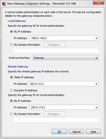
- In the Local Gateway section, select By IP Address.
- From the IP Address drop-down list, select the external IP address of the Firebox at Remote Office A, 198.51.100.2.
- From the External Interface drop-down list, select the primary external interface of the Central Office Firebox.
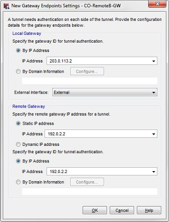
- In the Remote Gateway section, for Specify the remote gateway IP address, select Static IP address. In the adjacent text box, type the external IP address of the Central Office Firebox, 203.0.113.2.
- In the Specify the gateway ID for tunnel authentication section, select By IP Address. In the adjacent text box, type the external IP address of the Central Office Firebox, 203.0.113.2.
- Click OK to close the New Gateway Endpoints Settings dialog box.
The New Gateway dialog box opens. The gateway pair you defined opens in the list of gateway endpoints. - Click OK twice to close the New Gateway and Gateways dialog boxes.
Configure the Central Office Gateways
On the Central Office Firebox, use Policy Manager to configure the gateway that connects with Remote Office A.
- Select VPN > Branch Office Gateways.
The Gateways dialog box opens. - Click Add.
The New Gateway dialog box opens. - In the Gateway Name text box, type a name to identify this gateway in Policy Manager.
- In the Credential Method area of the General Settings tab, select Use Pre-Shared Key. Type the shared key in the adjacent text box.
- In the Gateway Endpoints section, click Add.
The New Gateway Endpoints Settings dialog box opens.
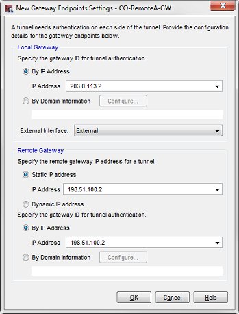
- In the Local Gateway section, select By IP Address.
- From the IP Address drop-down list, select the external IP address of the Central Office Firebox. For this example, select 203.0.113.2.
- From the External Interface drop-down list, select the primary external interface of the Central Office Firebox.
- In the Remote Gateway section, for Specify the remote gateway IP address, select Static IP address. In the adjacent text box, type the external IP address of the device at Remote Office A, 198.51.100.2.
- In the Specify the gateway ID for tunnel authentication section, select By IP Address. In the adjacent text box, type the external IP address of the device at Remote Office A, 198.51.100.2.
- Click OK to close the New Gateway Endpoints Settings dialog box.
The New Gateway dialog box opens. The gateway pair you defined opens in the list of gateway endpoints. - Click OK to close the New Gateway dialog box.
You return to the Gateways dialog box.
On the Central Office Firebox, configure the gateway that connects with Remote Office B.
- In the Gateways dialog box, click Add.
The New Gateway dialog box opens. - In the Gateway Name text box, type a name to identify this gateway in Policy Manager.
- In the Credential Method area of the General Settings tab, select Use Pre-Shared Key. Type the shared key in the adjacent text box.
- In the Gateway Endpoints section, click Add.
The New Gateway Endpoints Settings dialog box opens.
- In the Local Gateway section, select By IP Address.
- From the IP Address drop-down list, select the address.
- From the External Interface drop-down list, select the primary external interface of your Firebox.
- In the Remote Gateway section, for Specify the remote gateway IP address, select Static IP address. Type the external IP address of the device at Remote Office B in the adjacent text box.
- In the Specify the gateway ID for tunnel authentication section, select By IP Address. Type the external IP address of the device at Remote Office B in the adjacent text box.
- Click OK to close the New Gateway Endpoints Settings dialog box.
The New Gateway dialog box opens. The gateway pair you defined opens in the list of gateway endpoints. - Click OK twice to close the New Gateway and Gateways dialog boxes.
Configure the Remote Office B Gateway
On the Firebox at Remote Office B, use Policy Manager to configure the BOVPN gateway of Tunnel B that connects with the Central Office.
- Select VPN > Branch Office Gateways.
The Gateways dialog box opens. - Click Add.
The New Gateway dialog box opens. - In the Gateway Name text box, type a name to identify this gateway in Policy Manager.
- In the Credential Method area of the General Settings tab, select Use Pre-Shared Key. Type the shared key in the adjacent text box.
- In the Gateway Endpoints section, click Add.
The New Gateway Endpoints Settings dialog box opens.
- In the Local Gateway section, select By IP Address.
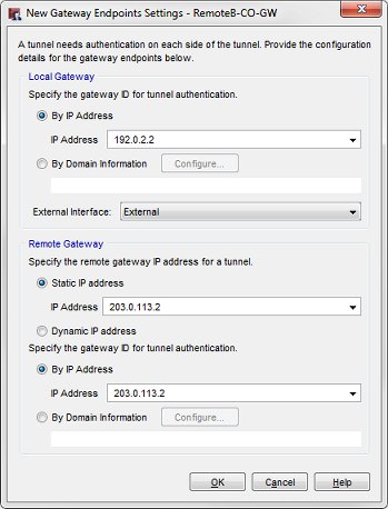
- From the IP Address drop-down list, select the external IP address of the Firebox at Remote Office B, 192.0.2.2.
- From the External Interface drop-down list, select the primary external interface of the Central Office Firebox.
- In the Remote Gateway section, for Specify the remote gateway IP address, select Static IP address. In the adjacent text box, type the external IP address of the Central Office Firebox, 203.0.113.2.
- In the Specify the gateway ID for tunnel authentication section, select By IP Address. In the adjacent text box, type the external IP address of the Central Office Firebox, 203.0.113.2 .
- Click OK to close the New Gateway Endpoints Settings dialog box.
The New Gateway dialog box opens. The gateway pair you defined opens in the list of gateway endpoints. - Click OK twice to close the New Gateway and Gateways dialog boxes.
Configure the Tunnel Routes
Before you define the BOVPN tunnel resources, keep in mind that the objective is to pass BOVPN traffic from the trusted network of Remote Office A to the trusted networks of Central office, and more importantly to the trusted network of Remote Office B. This can be achieved even if there is no direct BOVPN Tunnel between Remote Offices A and B.
Consider this diagram:
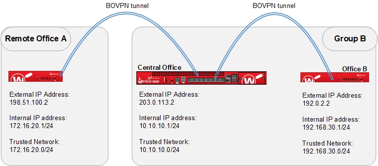
In this example, the Central Office and Remote Office B are grouped together and called Group B. This group represents the Tunnel Resources of the Central Office when the tunnel routes are defined between Remote Office A and the Central Office. From Remote Office A, the tunnel connects to both the trusted network of the Central Office (10.10.10.0/.24) and the trusted network of Remote Office B (192.168.30.0/24).
Configure Remote Office A Tunnel Routes that Connect to the Central Office
On the Firebox at Remote Office A, use Policy Manager to create two tunnel routes that go to the Central Office Firebox. One is for the private network of the Central Office, and the other is for the private network of Remote Office B.
- Select VPN > Branch Office Tunnels.
The Branch Office IPSec Tunnels dialog box opens. - Click Add.
The New Tunnel dialog box opens.
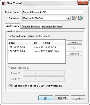
- In the Tunnel Name text box, type a name for the tunnel.
- From the Gateway drop-down list, select the gateway defined for Remote Office A.
- Click Add to add a tunnel route with these settings:
- Local: the trusted network address for this Firebox, 172.16.20.0/24
- Remote: the trusted network address of the Central Office Firebox, 10.10.10.0/24
- Direction: <===>
- Click Add to add a tunnel route with these settings:
- Local: the trusted network address of this Firebox, 172.16.20.0/24
- Remote: the trusted network address of the Remote Office B Firebox, 192.168.30.0/24
- Direction: <===>
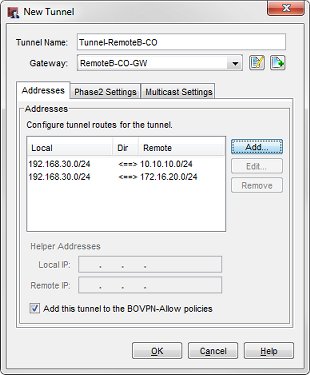
Configure Central Office Tunnel Routes that Connect to Remote Office A
On the Central Office Firebox, you must also use Policy Manager to configure two tunnel routes that go to Remote Office A. This allows the Central Office to use the private network of Remote Office B as if it was its own local network when it connects to Remote Office A.
- Select VPN > Branch Office Tunnels.
The Branch Office IPSec Tunnels dialog box opens. - Click Add.
The New Tunnel dialog box opens.
- In the Tunnel Name text box, type a name for the tunnel.
- From the Gateway drop-down list, select the gateway defined for Remote Office A.
- Click Add to add a tunnel route with these settings:
- Local: the trusted network address of the Central Office Firebox, 10.10.10.0/24
- Remote: the trusted network address of the Remote Office A Firebox, 172.16.20.0/24
- Direction: <===>
- Click Add to add a tunnel route with these settings:
- Local: the trusted network address of the Remote Office B Firebox, 192.168.30.0/24
- Remote: the trusted network address of the Remote Office A Firebox, 172.16.20.0/24
- Direction: <===>
Define the Tunnel Routes Between the Central Office and Remote Office B
To complete the Tunnel Switching configuration, you must do a similar but opposite configuration for the BOVPN tunnel between the Central Office and Remote Office B. This time, we group Remote Office A and the Central Office together and call it Group A. The tunnel routes between Central Office and the Remote Office B are configured afterwards.
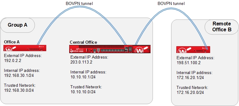
From Remote Office B, the tunnel connects to both the trusted network of Central Office (10.10.10.0/.24) and the trusted network of Remote Office A (172.16.20.0/24).
Configure Central Office Tunnel Routes that Connect to Remote Office B
On the Central Office Firebox, use Policy Manager to configure two tunnel routes that go to Remote Office B. This allows the Central Office to use the private network of Remote Office A as if it was its own local network when it connects to Remote Office B.
- Select VPN > Branch Office Tunnels.
The Branch Office IPSec Tunnels dialog box opens. - Click Add.
The New Tunnel dialog box opens.

- In the Tunnel Name text box, type a name for the tunnel.
- From the Gateway drop-down list, select the gateway defined for Remote Office B.
- Click Add to add a tunnel route with these settings:
- Local: the trusted network address of the Central Office Firebox, 10.10.10.0/24
- Remote: the trusted network address of the Remote Office B Firebox, 192.168.30.0/24
- Direction: <===>
- Click Add to add a tunnel route with these settings:
- Local: the trusted network address of the Remote Office A Firebox, 172.16.20.0/24
- Remote: the trusted network address of the Remote B Firebox, 192.168.30.0/24
- Direction: <===>
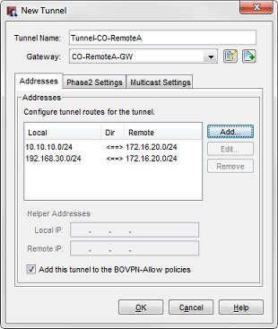
Configure Remote Office B tunnel routes that Connect to the Central Office
To complete the configuration, use Policy Manager to define two tunnel routes on the Edge X10e at Remote Office B that go to the Central Office. One is for the private network of the Central Office, and the other is for the private network of Remote Office A.
- Select VPN > Branch Office Tunnels.
The Branch Office IPSec Tunnels dialog box opens. - Click Add.
The New Tunnel dialog box opens.
- In the Tunnel Name text box, type a name for the tunnel.
- From the Gateway drop-down list, select the gateway defined for Remote Office B.
- Click Add to add a tunnel route with these settings:
- Local: the trusted network address for this Firebox, 192.168.30.0/24
- Remote: the trusted network address of the Central Office Firebox, 10.10.10.0/24
- Direction: <===>
- Click Add to add a tunnel route with these settings:
- Local: the trusted network address of this Firebox, 192.168.30.0/24
- Remote: the trusted network address of the Remote Office B Firebox, 172.16.20.0/24
- Direction: <===>
- Save the configuration changes to the Fireboxes at all three locations.
Check the Tunnel Switching Configuration
To see whether Tunnel Switching works, try to ping a computer on Remote Office B’s trusted network from Remote Office A’s trusted network. You must also make sure that the Central Office Firebox is not configured to deny ping attempts. If the ping is successful, you have configured Tunnel Switching correctly.
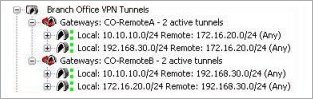
To verify that the tunnels are active, you can also look at Firebox System Manager for the Firebox at the Central Office. In Firebox System Manager, expand the Branch Office VPN tunnels section in the Front Panel to see the gateways and tunnels between each site. You might have to wait a moment for Firebox System Manager to connect to the Firebox before you can see status information. If Firebox System Manager on the Firebox at the Central Office shows that there are two BOVPN Gateways, each with two active tunnels, Tunnel Switching is configured correctly.
The active BOVPN Tunnels for the Central Office Firebox appear in Firebox System Manager.