BOVPN Virtual Interface for Dynamic Routing to Cisco
Topology
This configuration example shows how to configure a BOVPN virtual interface and OSPF dynamic routing between a Firebox and a Cisco virtual tunneling interface (VTI) on a Cisco router. For this example, the Cisco VTI is configured for IPSec tunnel mode, which does not use GRE. The Cisco VTI also supports GRE tunnel mode.
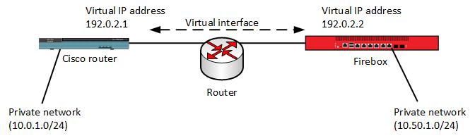
For this example, the two devices have these IP addresses:
Firebox IP addresses
External IP address — 203.0.113.2
Private network — 10.50.1.0/24
Virtual interface IP address — 192.0.2.2, netmask 255.255.255.0
Cisco router IP addresses
External IP address — 198.51.100.2/24
Private network — 10.0.1.0/24
Virtual interface IP address — 192.0.2.1, netmask 255.255.255.0
Firebox Configuration
In the BOVPN virtual interface configuration on the Firebox, you configure the local and remote gateway endpoints with the external IP addresses of the two devices. You must select the Cloud VPN or Third-Party Gateway endpoint type to configure an IPSec tunnel without GRE.
Gateway settings for this example:
Remote endpoint type — Cloud VPN or Third-Party Gateway
Credential method — Pre-shared Key
Gateway endpoint pair — Local (203.0.113.2), Remote (198.51.100.2)
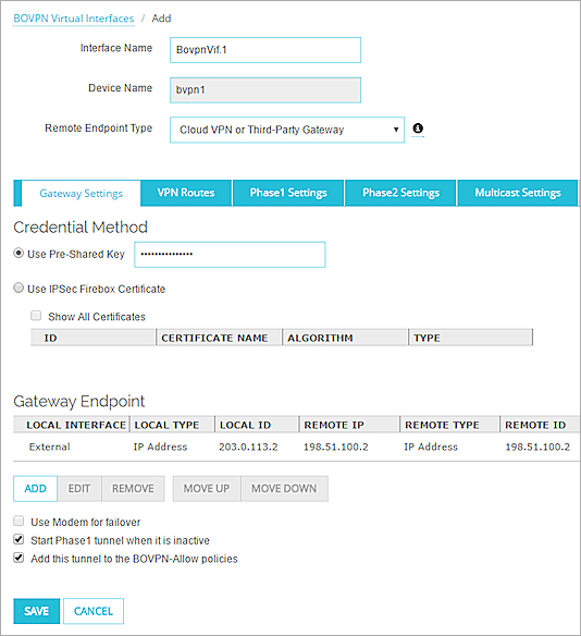
The configured gateway endpoint pair for the Firebox BOVPN virtual interface in Fireware Web UI
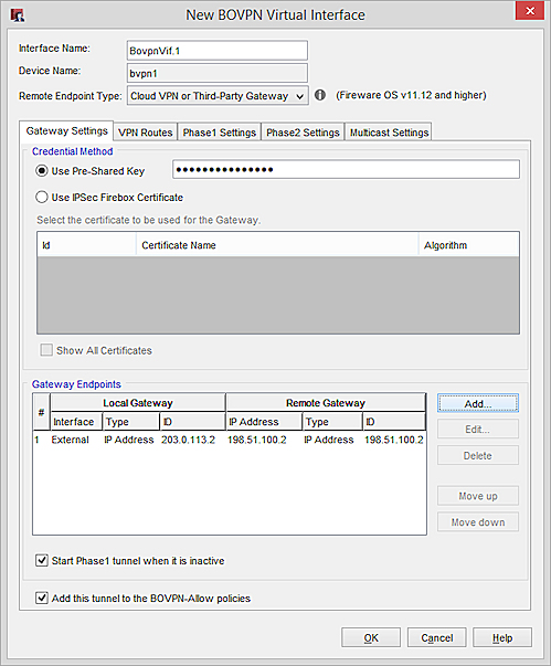
The configured gateway endpoint pair for the Firebox BOVPN virtual interface in Policy Manager
On the VPN Routes tab, the virtual IP address and netmask are configured for dynamic routing. The local IP address (192.0.2.2) is on the same subnet as the local IP address on the remote device, 192.0.2.1. On both devices, the netmask is 255.255.255.0.
For this example, the virtual interface IP address settings on the VPN Routes tab are:
Local IP address — 192.0.2.2
Peer IP address or netmask — 255.255.255.0
To use the BOVPN virtual interface for dynamic routing to a third-party VPN endpoint, you must configure the virtual interface IP address with a local IP address and a subnet mask. The virtual IP address on the Firebox must be on the same subnet as the virtual IP address of the peer VPN endpoint. On the Firebox, you configure a subnet mask, instead of the peer virtual IP address. For more information about virtual IP addresses, go to Virtual Interface IP Addresses for a VPN to a Third-Party Endpoint.
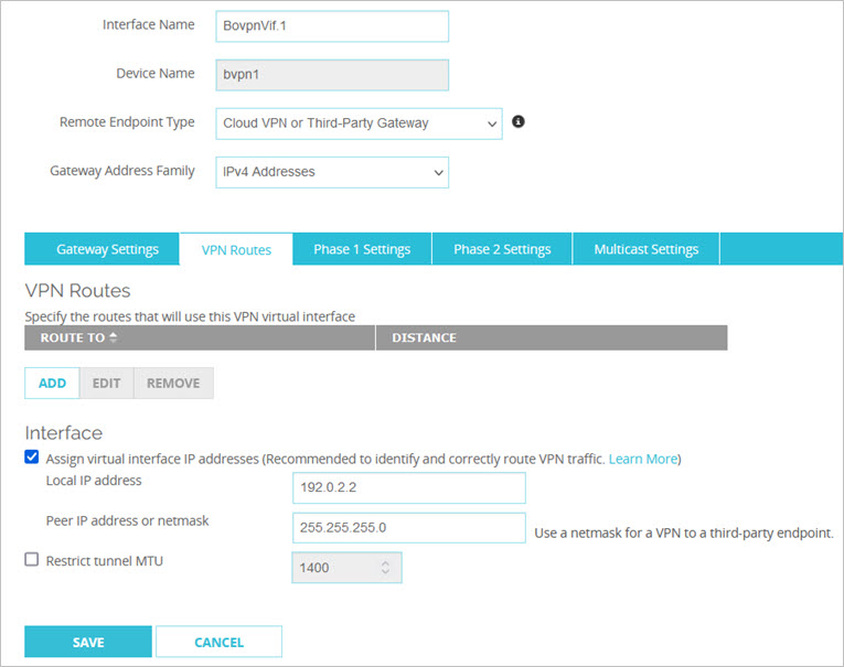
The configured virtual interface IP addresses in Fireware Web UI
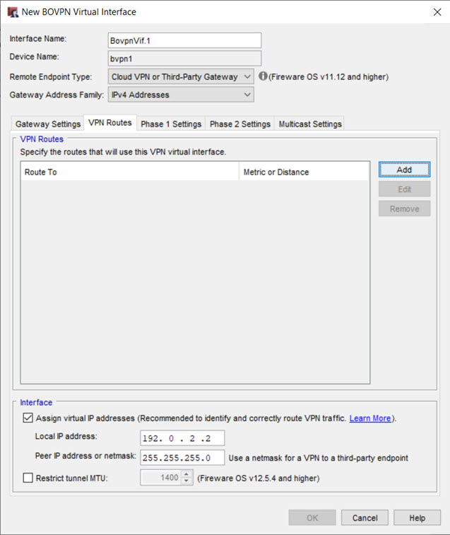
The configured virtual interface IP addresses in Policy Manager
The Phase 1 and Phase 2 settings on the Firebox and the Cisco device must match. For authentication, we recommend SHA-2, which is stronger than SHA-1 and MD5. For encryption, we recommend AES. Select AES (128-bit) for the best performance. Select AES (256-bit) for the strongest encryption.
Some WatchGuard and Cisco devices do not support SHA-2. If your device does not support SHA-2, use SHA-1. For more information, go to Add a Phase 1 Transform.
For this example, the Firebox uses these Phase 1 settings:
Version — IKEv2
Transform — SHA2-256, AES (256-bit)
Key Group — Diffie-Hellman Group 2
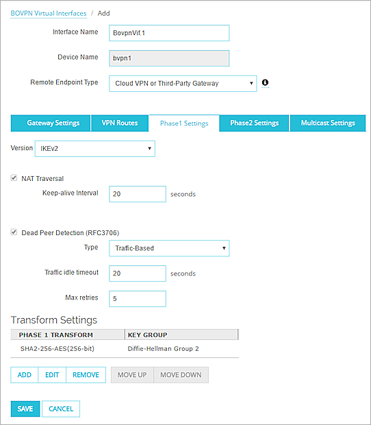
The configured Phase 1 settings in Fireware Web UI
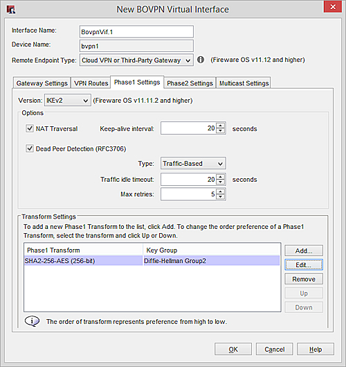
The configured Phase 1 settings in Policy Manager
Phase 2 settings on the Firebox:
Type — ESP
Authentication — SHA1
Encryption — AES (256-bit)
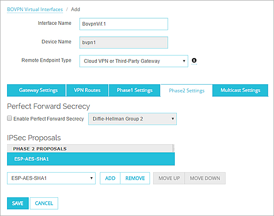
The configured Phase 2 settings in Fireware Web UI
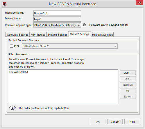
The configured Phase 2 settings in Policy Manager
The Firebox OSPF dynamic routing configuration has these commands:
interface bvpn1
ip ospf mtu-ignore
router ospf
network 192.0.2.0/24 area 0.0.0.0
network 10.50.1.0/24 area 0.0.0.0
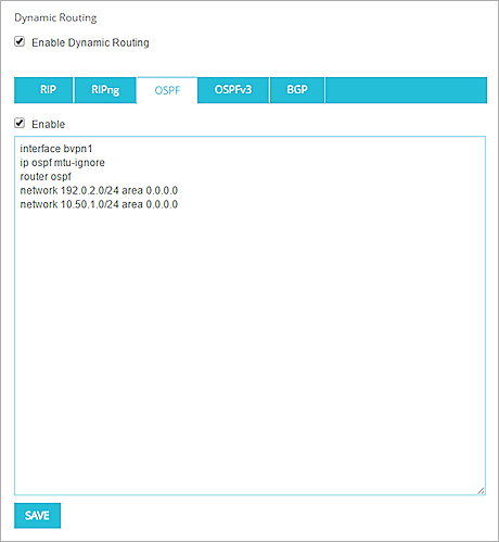
The configured OSPF settings in Fireware Web UI

The configured OSPF settings in Policy Manager
This configuration uses the mtu-ignore command to avoid MTU size issues with some Cisco routers.
Cisco Router Configuration
On the Cisco router, the configuration for this example has these commands:
crypto ikev2 keyring kyr1
peer peer1
address 203.0.113.2
pre-shared-key local key1
pre-shared-key remote key1
!
crypto ikev2 profile profile1
match identity remote address 203.0.113.2 255.255.255.255
identity local address 198.51.100.2
authentication local pre-share
authentication remote pre-share
keyring kyr1
!
crypto ipsec transform-set my-transform-set esp-aes 256 esp-sha256-hmac
!
crypto ipsec profile protect-ikev2
set security-association lifetime seconds 120
set transform-set my-transform-set
set ikev2-profile profile1
!
interface Tunnel1
ip address 192.0.2.1 255.255.255.0
ip ospf mtu-ignore
tunnel source 198.51.100.2
tunnel mode ipsec ipv4
tunnel destination 203.0.113.2
tunnel protection ipsec profile protect-ikev2
!
interface GigabitEthernet0/0
ip address 198.51.100.2 255.255.255.0
duplex auto
speed auto
!
interface GigabitEthernet0/1
ip address 10.0.1.1 255.255.255.0
duplex auto
speed auto
!
router ospf 1
network 10.0.1.0 0.0.0.255 area 0
network 192.0.2.0 0.0.0.255 area 0
!
Configure IPv4 Routing with OSPF
Virtual Interface IP Addresses for a VPN to a Third-Party Endpoint
Configure a BOVPN virtual interface that uses GRE for dynamic routing to Cisco (Fireware v11.11.x) in the WatchGuard Knowledge Base.